Magnetic suspension for a vehicle

A magnetic levitation, vehicle technology, applied in railway vehicles, vehicle parts, motor vehicles, etc., can solve problems such as bulky and expensive

Active Publication Date: 2019-04-02
IRONBOX SRL
View PDF8 Cites 0 Cited by
  • Summary
  • Abstract
  • Description
  • Claims
  • Application Information

AI Technical Summary

Problems solved by technology

The windings on the track are also bulky and expensive (copper for example) and the magnetic pads o

Method used


Image

  • Magnetic suspension for a vehicle
  • Magnetic suspension for a vehicle
  • Magnetic suspension for a vehicle

Examples


Embodiment Construction

[0095] In this document, the terms "vertical" or "horizontal" refer to the system used. In the picture:

[0096] - identical numbers indicate identical or conceptually similar parts;

[0097] - Letters N and S indicate North or South Magnetic Pole.

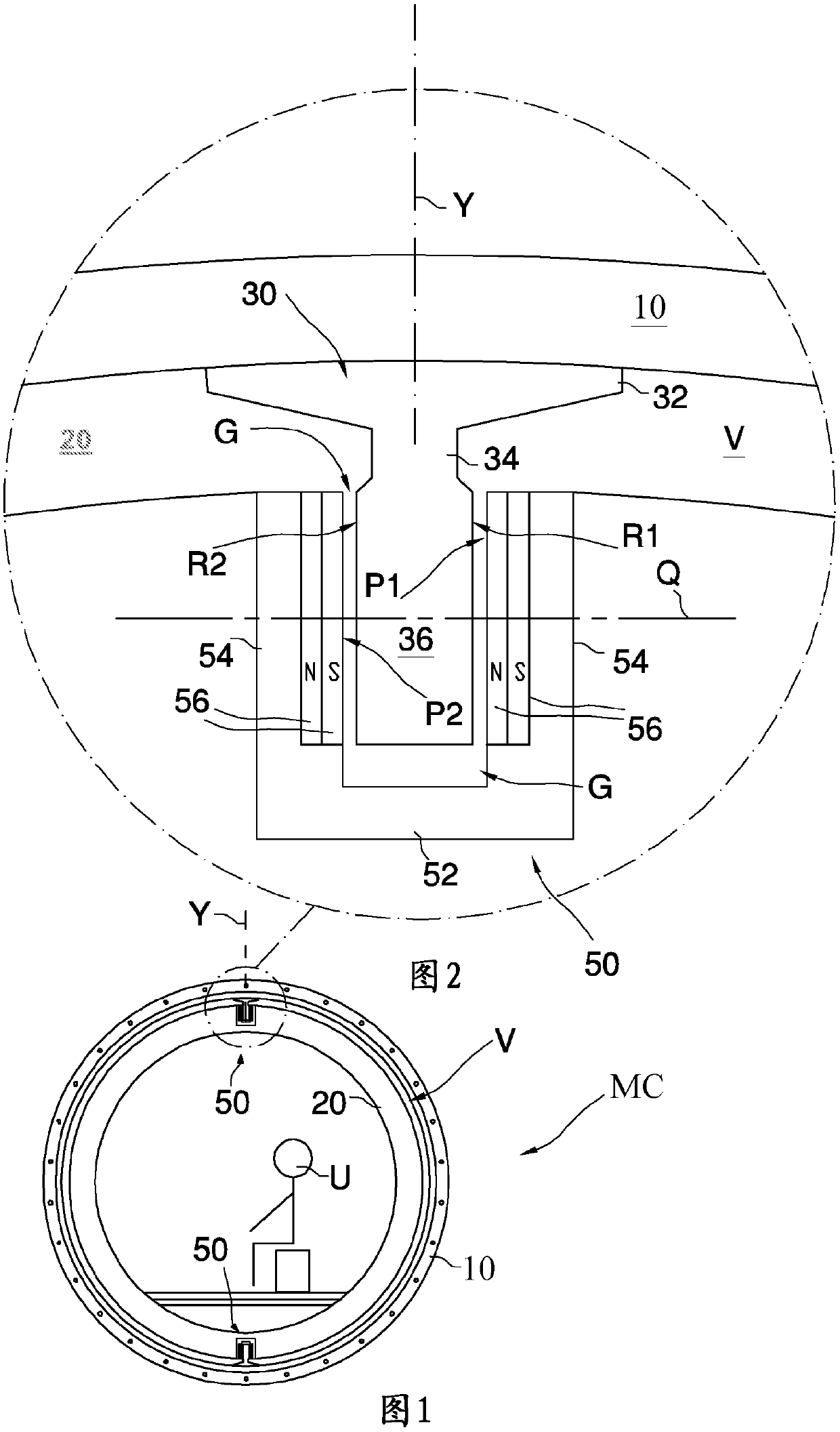
[0098] The levitation system MC for carrying a person or thing U comprises a tubular guide or structure 10 within which a cylindrical passenger compartment 20 of slightly smaller diameter is axially slid so as to maintain a gap therebetween. V.

[0099] At the top of the guide 10, a track 30 ( figure 2 ), the track 30 is slidably engaged with the magnetic slideway 50 installed on the passenger compartment 20 . The rail 30 includes a flange 32 intended to cooperate with the guide 10 from which a vertical neck 34 bearing a guide head 36 protrudes. The guide head 36 has a substantially rectangular cross-section, so that it comprises two main side surfaces R1 , R2 opposite to each other.

[0100] The slideway 50 is installed on...


PUM


Abstract

A magnetic suspension system (MC1; MC2; MC3) for a vehicle (20) is described comprising: a rail (30) made of material reactive to a magnetic field and comprising two opposite side surfaces (R1, R2); askid (50) which slides on the rail and, being substantially U-shaped, comprises two parallel arms (54) whose facing surfaces (P1, P2) delimit an empty space (G) partially occupied by the rail, each of the two opposed side surfaces of the rail, respectively facing one of the surfaces facing the two parallel arms, said skid being able to generate a magnetic field with a polar axis (Q) orthogonal tothose facing surfaces.

Description

technical field [0001] The present invention generally relates to a magnetic levitation device for a vehicle or passenger carriage, in particular public transport, such as a train as exemplified below. Background technique [0002] In order to improve the cruising speed, some trains leave the ground via a suspension system, which can be divided into two types: compressed air system (seeing US5909710) and magnetic field system (seeing US6664880 or Inductrack system). The first type blows high-pressure air under the train to form a pad; in the second type, magnets under the train create eddy currents inside the windings contained in the rails, which induce a supporting magnetic field. Each of these systems has disadvantages. [0003] Compressed air is produced by expensive, bulky turbines powered by massive amounts of energy. The windings on the track are also bulky and expensive (copper for example) and the magnetic pads only come in if the train is fast enough, otherwise a...

Claims


Application Information

Patent Timeline
IPC IPC(8): B60L13/04
CPCB60L13/04H01F1/032B60L2200/26B60Y2200/30
Inventor A·吉罗托
Owner IRONBOX SRL
Why Eureka
Try Eureka