Rotor and reluctance motor
A rotor and rotor core technology, applied in the direction of magnetic circuit, magnetic circuit rotating parts, magnetic circuit shape/style/structure, etc., can solve problems such as short-circuit current flow and energy efficiency reduction
- Summary
- Abstract
- Description
- Claims
- Application Information
AI Technical Summary
Problems solved by technology
Method used
Image
Examples
no. 2 approach
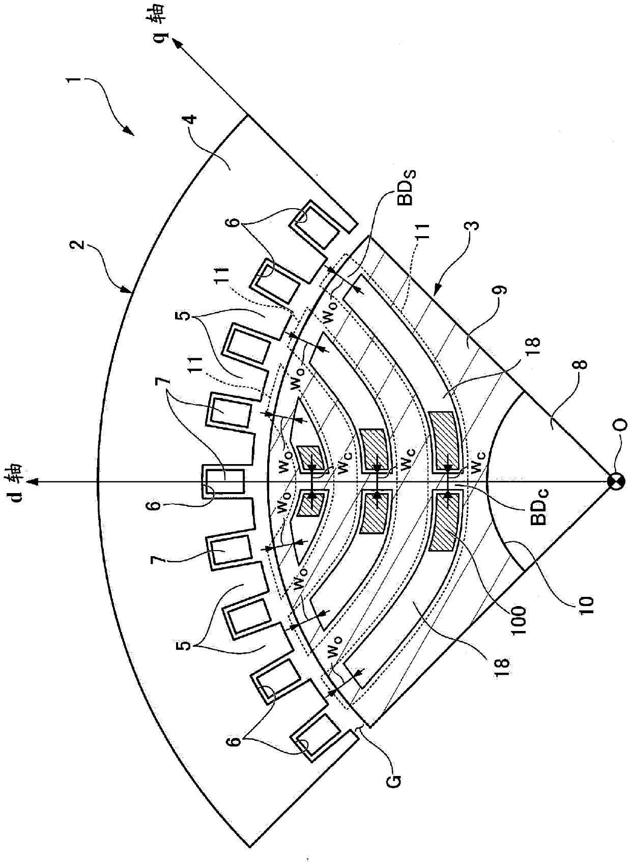
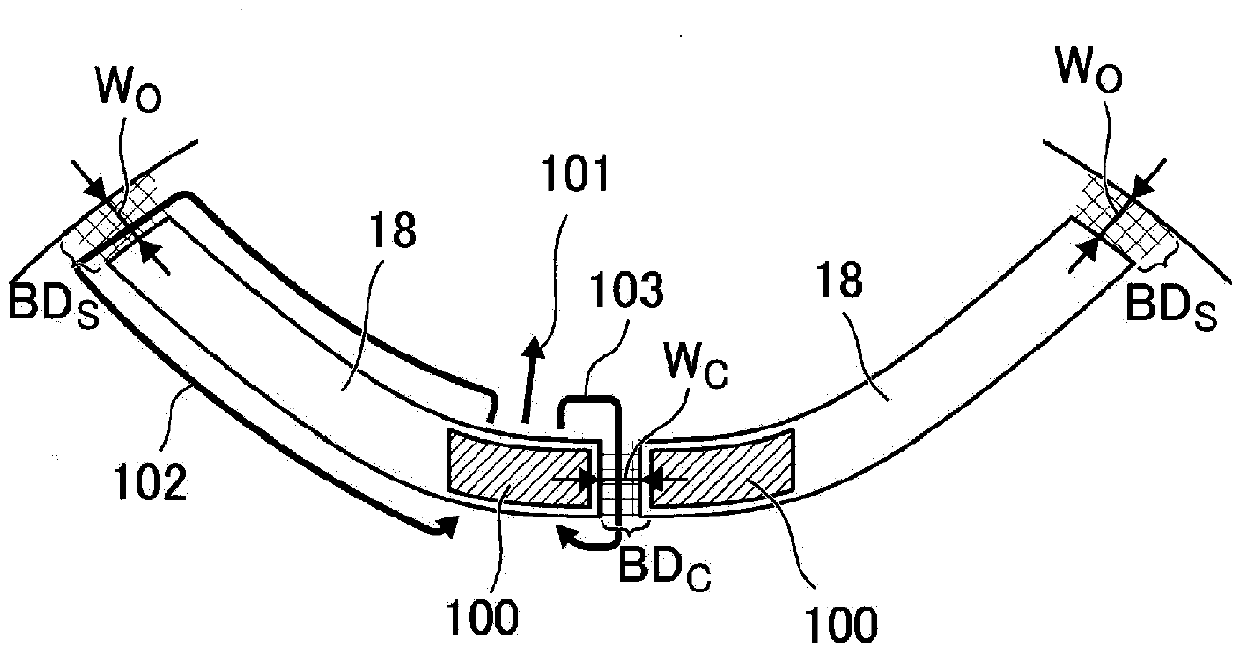
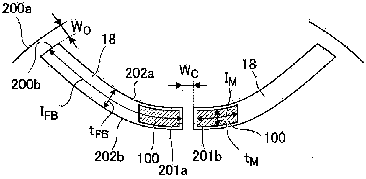
[0078] Hereinafter, a reluctance motor 1A according to the second embodiment will be described. Here, as a difference from the first embodiment, the center bridge BD is sandwiched between C The point that only one of the pair of barrier regions 18 is inserted with the permanent magnet 100 will be described. Hereinafter, descriptions of functions and the like common to those of the first embodiment described above will be omitted.
[0079] Figure 11 It is a cross-sectional view perpendicular to the rotating shaft 8 showing the structure of one pole of the reluctance motor 1A of the second embodiment. In the second embodiment, sandwiching the center bridge BD C The permanent magnet 100 is inserted in only one of the pair of barrier regions 18 , and a weight adjustment member WT having a mass similar to that of the permanent magnet 100 is inserted in the other barrier region 18 . That is, the permanent magnet 100 is arranged in the barrier region 18 biased to one side with r...
no. 3 approach
[0090] Hereinafter, a reluctance motor 1B according to a third embodiment will be described. Here, as a difference from the first and second embodiments, there is no center bridge BD C or peripheral bridge BD S Either side of this will be explained. Hereinafter, descriptions of functions and the like common to those of the first and second embodiments described above will be omitted.
[0091] Figure 13 It is a cross-sectional view perpendicular to the rotating shaft 8 showing the structure of one pole of the reluctance motor 1B of the third embodiment. In the third embodiment, only the peripheral bridge BD exists S , each flux barrier 11 has one barrier region 18 . In this case, in the above formula (1), it can be obtained by setting w B as 2w o To determine the size of the permanent magnet 100. In addition, in Figure 13 In , only the flux barrier 11 closest to the central axis O is marked with a sign of 18 indicating a barrier region and a sign of 100 indicating a ...
no. 4 approach
[0096] Hereinafter, a reluctance motor 1C according to a fourth embodiment will be described. Here, as a point different from the first to third embodiments, the point that three or more barrier regions 18 are formed will be described. Hereinafter, descriptions of functions and the like common to those of the first to third embodiments described above will be omitted.
[0097] Figure 14 It is a cross-sectional view perpendicular to the rotating shaft 8 showing the configuration of one pole of the reluctance motor 1C according to the fourth embodiment. exist Figure 14In , only the flux barrier 11 closest to the central axis O is marked with a sign of 18 indicating a barrier region and a sign of 100 indicating a permanent magnet, and the same applies to the other flux barriers 11 . In addition, the divided barrier regions are shown as 18a, 18b, 18c. In the fourth embodiment, since three barrier regions 18 are formed in each magnetic flux barrier 11, two central bridge port...
PUM
 Abstract
Description
Claims
Application Information
 - R&D
- Intellectual Property
- Life Sciences
- Materials
- Tech Scout
- Unparalleled Data Quality
- Higher Quality Content
- 60% Fewer Hallucinations
Browse by: Latest US Patents, China's latest patents, Technical Efficacy Thesaurus, Application Domain, Technology Topic, Popular Technical Reports.
© 2025 PatSnap. All rights reserved.Legal|Privacy policy|Modern Slavery Act Transparency Statement|Sitemap|About US| Contact US: help@patsnap.com


