Pole piece punching device capable of automatically removing leftover materials for battery production

A technology for automatic removal of leftovers, applied in the direction of cleaning methods using gas flow, stripping devices, cleaning methods and utensils, etc., can solve problems affecting work efficiency, unfavorable cleaning, inconvenient waste disposal, etc., to ensure normal operation and prevent omissions Lost, increased friction effects

Active Publication Date: 2019-04-05
SHANGHAI QINXUAN INFORMATION TECH CO LTD
View PDF8 Cites 4 Cited by
  • Summary
  • Abstract
  • Description
  • Claims
  • Application Information

AI Technical Summary

Problems solved by technology

[0004] The object of the present invention is to provide a pole piece punching device that can automatically remove leftovers for battery production, so as to solve the problem that the existing pole piece punching device proposed in the above background technology can only perform a single cutting or cutting of battery pole pieces. Compression molding it, in the process of punching the pole piece, cannot quickly collect and collect the waste after punching, so that it is not convenient to deal with the waste after punching the pole piece, and the leftovers produced by punching are usually accumulated to the A certain amount is collected and processed. This processing method causes a large amount of leftovers to accumulate around the punching device, which affects the working environment of the user and is not conducive to its cleaning, thus affecting its work efficiency.

Method used


Image

  • Pole piece punching device capable of automatically removing leftover materials for battery production
  • Pole piece punching device capable of automatically removing leftover materials for battery production
  • Pole piece punching device capable of automatically removing leftover materials for battery production

Examples


Embodiment Construction

[0026] The following will clearly and completely describe the technical solutions in the embodiments of the present invention with reference to the accompanying drawings in the embodiments of the present invention. Obviously, the described embodiments are only some, not all, embodiments of the present invention. Based on the embodiments of the present invention, all other embodiments obtained by persons of ordinary skill in the art without making creative efforts belong to the protection scope of the present invention.

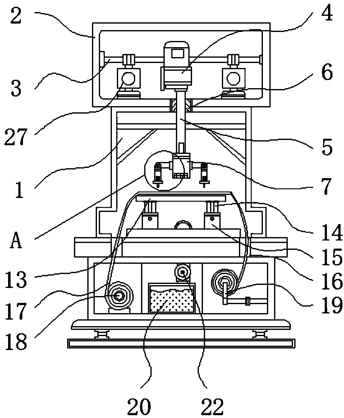
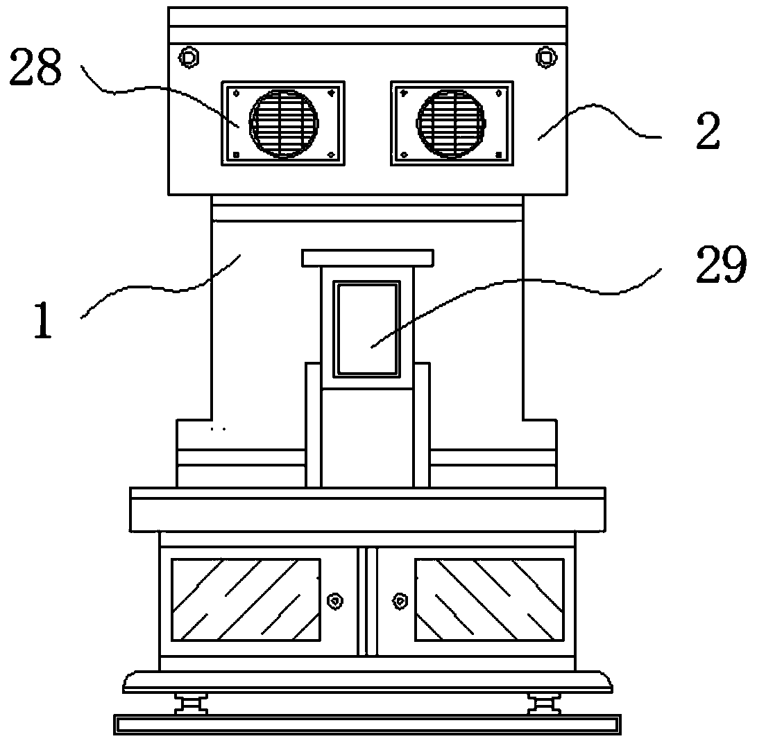
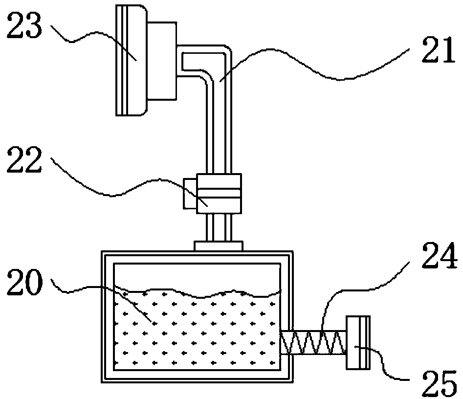
[0027] see Figure 1-5 , the present invention provides a technical solution: a pole piece punching device that can automatically remove scraps for battery production, including a device body 1, a top layer 2, a fixed rod 3, a hydraulic pump 4, a hydraulic rod 5, a movable groove 6, a punching Cutting block 7, friction pad 8, rotating rod 9, rotating shaft 10, spring 11, punching knife 12, placing table 13, extension rod 14, telescopic rod 15, sliding groove 1...


PUM


Abstract

The invention relates to a pole piece punching device capable of automatically removing leftover materials for battery production. The pole piece punching device comprises a device body, a friction pad and a placing table. A top layer is fixed to the upper end of the device body, and the top layer is internally provided with a fixing rod. A hydraulic pump is connected to the front end of the fixedrod in a welded mode, and a hydraulic rod is fixed to the lower end of the hydraulic pump. The outer part of the hydraulic rod is wrapped with a moveable groove, and a punching block is arranged at the lower end of the hydraulic rod. The friction pad is disposed at the lower end of the punching block, and rotating rods are fixed to the left end and the right end of the punching block. Rotating shafts are mounted on the outer sides of the rotating rods, and springs are disposed at the lower ends of the rotating shafts. According to the pole piece punching device capable of automatically removing the leftover materials for the battery production, the hydraulic pump and the punching block constitute a telescopic structure through the hydraulic rod, the hydraulic rod and the movable groove constitute a movable structure, the hydraulic pump in the top layer is started to enable the hydraulic pump to drive the rod to extending downwards, and at the same time, the hydraulic rod slides in themovable groove.

Description

technical field [0001] The invention relates to the technical field of battery production, in particular to a pole piece punching device for battery production that can automatically remove scraps. Background technique [0002] Various equipment used in the battery production process, stamping processing is the power of conventional or special stamping equipment, so that the sheet is directly subjected to deformation force and deformed in the mold, so as to obtain product parts of a certain shape, size and performance Production technology, using a knife die, is "punching", bending the blade into the desired shape, and "punching" the sheet through punching or pressing equipment to obtain the product. This method is punching. In the battery production process Need to punch the pole piece. [0003] The existing pole piece punching device usually can only single-cut or press-mold the battery pole piece. During the pole piece punching process, it cannot quickly collect and coll...

Claims


Application Information

Patent Timeline
Patent Type & Authority Applications(China)
IPC IPC(8): B21D28/02B21D45/00B08B5/04
CPCB08B5/04B21D28/02B21D45/00
Inventor 罗美羚
Owner SHANGHAI QINXUAN INFORMATION TECH CO LTD
Why Eureka
Try Eureka