Thrust line display adjustment method and adjustment device of UAV booster rocket

A technology for adjusting devices and UAVs, applied in the direction of launching/dragging transmission devices, etc., can solve problems such as complex device or platform structure design, achieve good use and promotion effects, ingenious ideas, and intuitive display effects

Active Publication Date: 2022-02-18
NO 60 RES INST OF GENERAL STAFF DEPT PLA
View PDF14 Cites 0 Cited by
  • Summary
  • Abstract
  • Description
  • Claims
  • Application Information

AI Technical Summary

Problems solved by technology

[0005] The above adjustment positioning device or adjustment platform failed to visually display the thrust line, and high-value equipment such as three-way digital display displacement regulator and digital dual-axis angle sensor were used, and the structural design of the device or platform was relatively complicated

Method used


Image

  • Thrust line display adjustment method and adjustment device of UAV booster rocket
  • Thrust line display adjustment method and adjustment device of UAV booster rocket
  • Thrust line display adjustment method and adjustment device of UAV booster rocket

Examples


Embodiment Construction

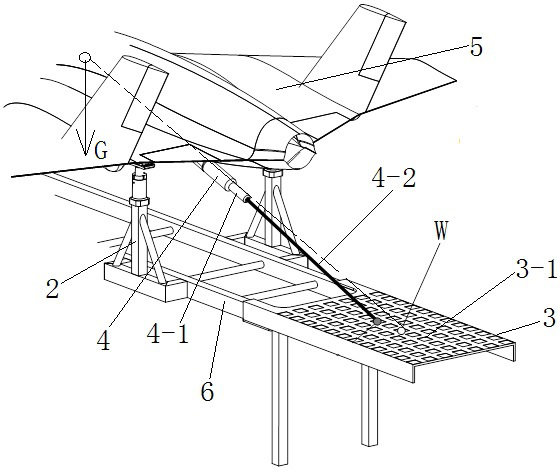
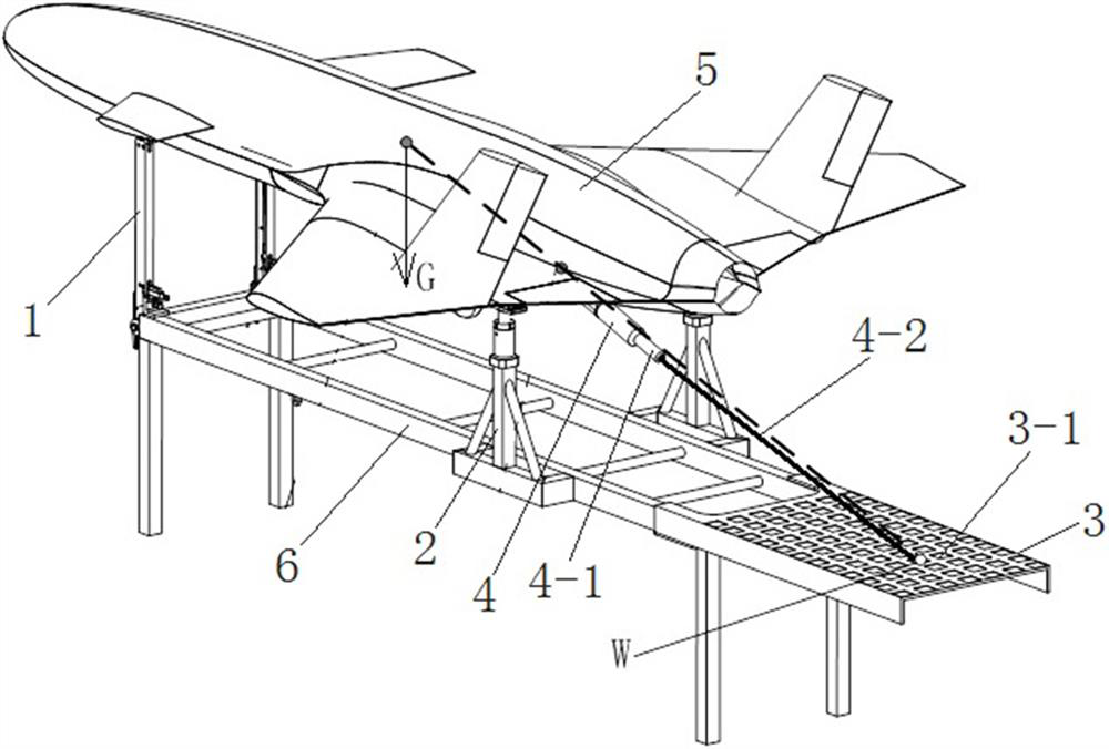
[0027] Refer to attached Figure 1-3 , the thrust line display adjustment device of the UAV booster rocket has a frame, a front support column 1 is arranged at the front end of the frame, and a rear support column 2 is provided at the rear end; the number of the rear support columns 2 is a pair, respectively located at Both sides of the frame; at the tail end of the frame, a matrix adjustment grid 3 is arranged behind the rear support column 2, and the matrix adjustment grid 3 is horizontal to the ground; a plurality of rectangular grids are arranged on the matrix adjustment grid 3 The grid 3-1 of the array or honeycomb array is used to display different coordinate parameters; the rocket simulator 4 is matched with the matrix adjustment grid 3, and the size of the rocket simulator 4 is equal to that of a real booster rocket. The tail end of 4 is provided with laser launcher 4-1, and the beam 4-2 direction of laser launcher 4-1 coincides with the thrust direction of booster roc...


PUM


Abstract

The invention relates to a display adjustment method for adjusting the thrust line of an unmanned aerial vehicle booster rocket and an adjustment device used in the adjustment method. The thrust line display adjustment device of the UAV booster rocket has a frame, a front support column is arranged at the front end of the frame, and a rear support column is provided at the rear end; the number of the rear support columns is a pair, which are respectively located on two sides of the frame side; at the rear end of the frame, a matrix adjustment grid is arranged behind the rear support column, and the matrix adjustment grid is horizontal to the ground; on the matrix adjustment grid, a plurality of grids of rectangular arrays or honeycomb arrays are arranged. The grid is used to display different coordinate parameters; the matrix adjustment grid is matched with a rocket simulator, the size of the rocket simulator and the real booster rocket, and a laser transmitter is set at the tail end of the rocket simulator. The beam direction coincides with the thrust direction of the booster rocket, and the rocket simulator is installed on the push seat provided on the belly of the UAV.

Description

technical field [0001] The invention relates to an adjustment method for adjusting the thrust line of an unmanned aerial vehicle booster rocket and an adjustment device used in the adjustment method. Background technique [0002] Rocket-assisted, zero-length launch and take-off are the most commonly used take-off methods for small and medium-sized fixed-wing UAVs. This method has relatively low requirements for the take-off environment, does not require a dedicated airport, and can well meet the requirements for field use of drones. However, when UAVs perform different tasks, they need to mount different mission equipment. These devices are often different in size and weight, and mounting them on the UAV will also change the center of gravity of the UAV. Before launching, it is necessary to adjust the space state of the booster rocket to ensure the smooth take-off of the UAV. [0003] In the traditional UAV launch infield preparation process, the UAV is usually turned over...

Claims


Application Information

Patent Timeline
Patent Type & Authority Patents(China)
IPC IPC(8): B64F1/04
CPCB64F1/04
Inventor 王晓东
Owner NO 60 RES INST OF GENERAL STAFF DEPT PLA
Why Eureka
Try Eureka