
Continuous oil pipe injection device, injection method, and method for changing oil pipe with non-stop pump

A technology of oil pipe and hoisting device, which is applied in the direction of wellbore/well valve device, earthwork drilling and production, wellbore/well components, etc. It can solve the problems of oil field economic loss, reduction of liquid production, oil well overhaul accidents, etc., and achieve Effect of reducing work difficulty and reducing work cost

Active Publication Date: 2021-05-14
RES INST OF SHAANXI YANCHANG PETROLEUM GRP
View PDF6 Cites 0 Cited by
  • Summary
  • Abstract
  • Description
  • Claims
  • Application Information

AI Technical Summary

Problems solved by technology

Since horizontal wells are often developed by large-scale multi-stage fracturing, the phenomenon of fracturing sand back-vomiting is relatively common, which will result in a decrease in fluid production and, in severe cases, problems in sand-buried reservoirs. Well washing and sand flushing must be carried out in time to ensure The bottom of the well is clean, and the oil well can produce normally
When performing conventional sand flushing, it is necessary to carry out tubing operation, and the pump needs to be stopped during the tubing connection process. However, due to the special wellbore structure of horizontal wells, once the pump is stopped, the suspended sand is easy to settle. A sand bridge is formed in the horizontal well section, and the oil pipe is stuck. If the jam is not released in time, it will cause an oil well overhaul accident, and in severe cases, the oil well may even be scrapped, bringing huge economic losses to the oil field.
Although there is coiled tubing technology that can avoid the operation of the connecting string, its promotion in low-permeability oilfields is limited due to its high cost of use. Therefore, a set of equipment and technology is urgently needed to solve this problem, and to develop oilfields for horizontal wells. Improve strong technical support

Method used


Image

  • Continuous oil pipe injection device, injection method, and method for changing oil pipe with non-stop pump
  • Continuous oil pipe injection device, injection method, and method for changing oil pipe with non-stop pump

Examples


Embodiment 1

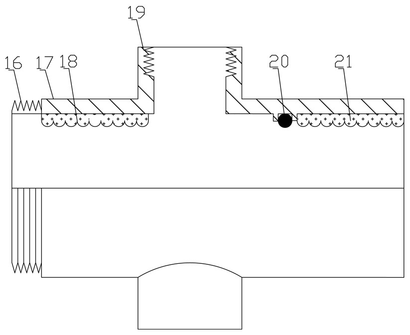
[0027] A continuous tubing injection device, comprising a main body seat 17 and a main pipe body 2 sleeved in the main body seat 17; wherein, the main body seat 17 is provided with a wellhead connection end 16 and an injection pipeline connection end 17, and the main body seat 17 is connected to the wellhead; The main body 2 is a round pipe; the two ends of the main body 2 are provided with an upper joint 15 and a lower joint 1 for connecting oil pipes, the main body 2 is provided with a liquid inlet hole 7, and the main body 2 is sleeved with a sliding opening. Closing device; the sliding opening and closing device includes a sliding sleeve main body 6 and a sliding sleeve return spring 10, and the end of the sliding sleeve main body away from the sliding sleeve returning spring 10 is provided with a sliding sleeve opening and closing gear; the main body seat is provided with a sliding sleeve The sleeve opening and closing gear is matched with the elastic steel ring used to co...

Embodiment 2

[0029] A continuous oil pipe injection method, using the oil pipe continuous injection device as described above, the method is as follows:

[0030] The main body seat 17 is connected to the wellhead through the wellhead connection end 16, and the injection pipeline is connected to the injection line connection end 17; the upper oil pipe is connected to the upper joint 15, and the lower oil pipe is connected to the lower joint 1; the upper oil pipe is connected to the injection line, and the lower oil pipe passes through the main seat 17 lowered into the well;

[0031] In the initial downward stage of the main body 2, the valve ball 11 is under the force of the valve ball return spring 12, and the contact and seal between the valve ball 13 and the valve seat 14; When it is greater than the spring force of the valve ball return spring 12, the valve ball 13 is pushed back, so that the valve ball return spring 12 is elastically deformed, the one-way valve is opened, and the well ...

Embodiment 3

[0035] A method for changing oil pipes with non-stop pumps, using the above-mentioned oil pipe continuous injection device, the method is as follows:

[0036] The main body seat 17 is connected to the wellhead through the wellhead connection end 16, and the injection pipeline is connected to the injection line connection end 17; the upper oil pipe is connected to the upper joint 15, and the lower oil pipe is connected to the lower joint 1; the upper oil pipe is connected to the injection line, and the lower oil pipe passes through the main seat 17 lowered into the well;

[0037] In the initial downward stage of the main body 2, the valve ball 13 is under the force of the valve ball return spring 12, and the contact between the valve ball 13 and the valve seat 14 is sealed; When it is greater than the spring force of the valve ball return spring 12, the valve ball 13 is pushed back, so that the valve ball return spring 12 is elastically deformed, the one-way valve is opened, an...


PUM


Abstract

The invention relates to an oil pipe continuous injection device, an injection method and a method for changing the oil pipe without stopping the pump. The oil pipe continuous injection device, the injection method and a method for changing the oil pipe without stopping the pump include a main body seat and a main body pipe sleeved in the main body seat; wellhead connection; the main pipe is a round pipe; the two ends of the main pipe are provided with an upper joint and a lower joint for connecting the oil pipe, the main pipe is provided with a liquid inlet hole, and the main pipe is sleeved with a sliding opening and closing device; The sliding opening and closing device includes a sliding sleeve main body and a sliding sleeve return spring. The sliding sleeve main body is provided with a sliding sleeve opening and closing gear; the main body seat is provided with an elastic steel ring corresponding to the sliding sleeve opening and closing gear; it also includes a hollow One end of the one-way valve body is connected to the upper joint, and the other end is connected to the main pipe; the one-way valve body is sequentially provided with a valve ball and a valve ball return spring. The invention ensures the continuous injection of well flushing fluid.

Description

technical field [0001] The invention relates to a continuous injection device, an injection method, and a method for continuously pumping and changing oil pipes, which are specially used for high-inclination oil well washing and sand washing. Background technique [0002] Since horizontal wells were used in the development of low-permeability oilfields, their well structure characteristics and technical advantages have brought oil well single-well production and oilfield recovery to a new level, so people have paid more and more attention to and favored them. Horizontal wells The number is also gradually increasing. Because horizontal wells are often developed by large-scale multi-stage fracturing, the phenomenon of fracturing sand back-vomiting is relatively common, which will result in a decrease in fluid production and, in severe cases, the problem of sand-buried reservoirs. Well washing and sand washing must be carried out in time to ensure Only when the bottom of the w...

Claims


Application Information

Patent Timeline
Patent Type & Authority Patents(China)
IPC IPC(8): E21B21/00E21B37/00E21B34/08
CPCE21B21/00E21B34/08E21B37/00
Inventor 高庆华申峰赵习森赵亚杰刘通符喜德刘建刚李国明杨洪段景杰
Owner RES INST OF SHAANXI YANCHANG PETROLEUM GRP
Learn More