Combined structure of impeller

A combined structure and impeller technology, which is applied in liquid fuel engines, mechanical equipment, buildings, etc., can solve the problems of relatively tight blade design and loud noise, and achieve good mute effect, reduce noise, and increase air suction volume Effect

Inactive Publication Date: 2019-04-05
浙江卓远机电科技股份有限公司
View PDF7 Cites 1 Cited by
  • Summary
  • Abstract
  • Description
  • Claims
  • Application Information

AI Technical Summary

Problems solved by technology

[0003] Generally speaking, the more blades the electric fan has, the better the air supply effect will be. Although it will increase the load, the more blades, the "wind" can be cut into smaller pieces, making the wind blown more Soft, quiet effect is better, but because the impeller is a one-piece structure, for the sake of demoulding, the blades will not be designed closer
Secondly, the traditional impeller structure is used in the air duct, and the inhaled air will directly hit the wind blade surface vertically to generate a lot of noise, and the air duct of some machines is curved, but the air will eventually hit the impeller vertically

Method used


Image

  • Combined structure of impeller
  • Combined structure of impeller
  • Combined structure of impeller

Examples


Embodiment Construction

[0017] The present invention will be further described below in conjunction with the accompanying drawings and embodiments.

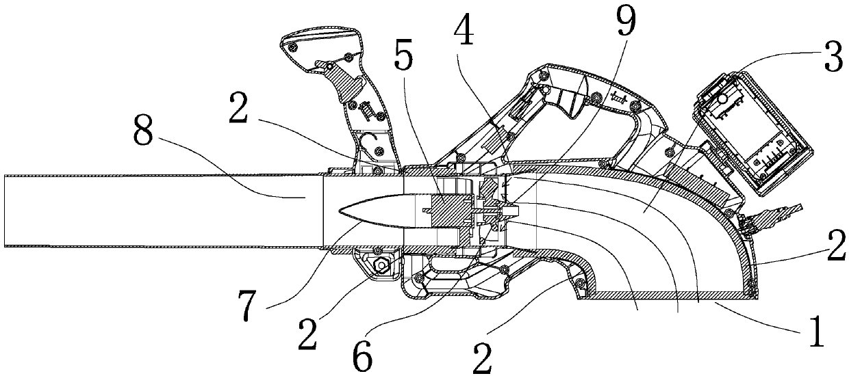
[0018] Figure 1-Figure 2 The inside of the middle blower includes the air channel cavity 3, the air inlet 1 and the air outlet 8, and the air inlet 1 is designed to open downward, so that the operator has the least impact when holding it. A sponge sheet 2 is arranged in the air duct cavity 3, and the sponge sheet 2 fills up the air duct cavity 3 to eliminate concave and convex areas in the air duct cavity 3, so that whistles cannot be produced. Since the sponge sheet 2 itself is porous, the sponge sheet 2 also has the function of sound absorption.

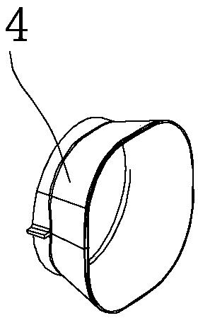
[0019] The impeller 6 of the present invention is horizontally blocked in the air channel chamber 3, and a motor 5 is provided to drive the impeller 6 to rotate. The front of the impeller 6 is provided with a shroud 4, the shroud 4 is trumpet-shaped, and the shroud 4 has a large mouth. Facing the air inle...


PUM


Abstract

The invention provides a combined structure of an impeller. The combined structure of the impeller comprises a plurality of blade units, wherein the blade units are circumferentially spliced to form the impeller, the impeller is transversally stop in an air channel cavity, each blade unit comprises a splicing main body and an inclined blade, the two sides of each splicing main body are planes, theplanes of the adjacent splicing main bodies are next to each other, the splicing main bodies encircle a circular ring and the middle of the circular ring is hollow, grooves are formed in an upper position and a lower position of each splicing main body, the upper positions and the lower positions form an annular groove after the splicing main bodies are spliced, and a concentric circular cover playing the role of limiting sleeves into the annular groove; and the blades are arrayed along the axis of the circular ring after being spliced, and in the axial direction of the circular ring, the lower end of each front blade and the upper end of the adjacent rear blade are locally superposed. According to the combined structure of the impeller, the number of the blades on the impeller can be increased, wind can be cut into smaller pieces while an air suction amount is increased, and a better silencing effect is achieved; and the impeller and the inclined surface of a flow guide cover are capable of bouncing inlet air to form eddy, so that air cannot vertically collide with the rotary surfaces of the blades, and noise is also lowered.

Description

technical field [0001] The invention relates to the field of electric tools, in particular to an impeller combination structure. Background technique [0002] High-power hair dryers are often accompanied by loud noises. After careful study of the noise source, we found that the noise of the air duct is closely related to the impeller. [0003] Generally speaking, the more blades the electric fan has, the better the air supply effect will be. Although it will increase the load, the more blades, the "wind" can be cut into smaller pieces, making the wind blown more Soft, quiet effect is better, but because the impeller is a one-piece structure, for the sake of demoulding, the design of the blades will not be relatively tight. Secondly, the traditional impeller structure is used in the air duct, and the inhaled air will directly hit the wind blade surface vertically to generate a lot of noise, and some machines have curved air ducts, but the air will eventually hit the impeller...

Claims


Application Information

Patent Timeline
Patent Type & Authority Applications(China)
IPC IPC(8): F04D29/32F04D29/38F04D29/54F04D29/66
CPCE01H1/0809F04D29/325F04D29/388F04D29/541F04D29/545F04D29/664
Inventor 周海军杨岳峰罗恒
Owner 浙江卓远机电科技股份有限公司
Why Eureka
Try Eureka