
IGBT module parallel temperature detecting circuit

A technology of temperature detection circuit and analog switch circuit, which is applied to thermometers, thermometers using directly heat-sensitive electrical/magnetic components, measuring devices, etc., can solve the temperature detection runaway state, increase sampling cost, electromagnetic interference and detection response time increase etc.

Pending Publication Date: 2019-04-05
NANJING APAITEK TECH
View PDF0 Cites 5 Cited by
  • Summary
  • Abstract
  • Description
  • Claims
  • Application Information

AI Technical Summary

Problems solved by technology

With the continuous improvement of the power level of power electronic devices and the increasing restrictions on cost reduction requirements, the IGBT parallel scheme has been used more in the industry. However, due to the limited temperature sampling circuit cost and space requirements, most of the current industry uses parallel IGBT schemes. In this method, only one single module is used for temperature detection, or the cost of one-way sampling is increased, and the circuit space is compressed for temperature detection of two modules.
[0003] The above two detection schemes have the following disadvantages: 1) Only one single module is tested for temperature, resulting in the temperature detection of another module connected in parallel is out of control; Strong electromagnetic interference capability and other requirements require an isolation detection scheme, which will increase the sampling cost of one circuit, and the three-phase IGBT circuit will naturally have three circuits; 3) Due to the limited space, the space between the electronic components of the circuit must be reduced if the space cannot be increased. , increase the three-way sampling processing conditioning circuit, the electromagnetic interference and detection response time have significantly increased

Method used


Image

  • IGBT module parallel temperature detecting circuit
  • IGBT module parallel temperature detecting circuit

Examples


Embodiment Construction

[0021] The present invention will be specifically described below in conjunction with the accompanying drawings.

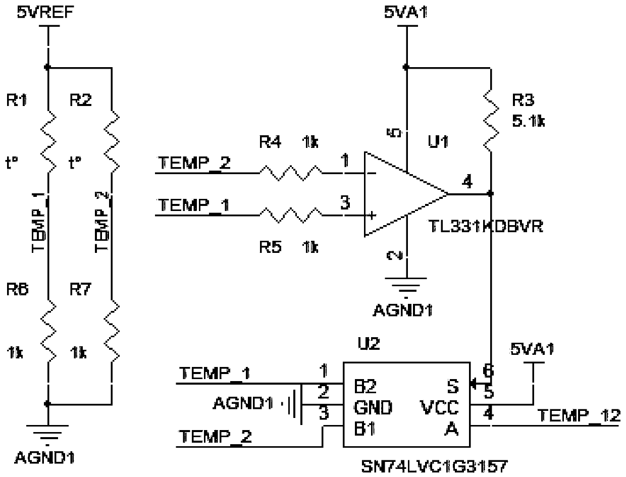
[0022] A kind of IGBT module parallel connection temperature detection circuit, is used for detecting the temperature of two-way parallel connection IGBT module, is characterized in that: comprise voltage divider circuit, comparator circuit, analog switch circuit, sampling follow conditioning circuit, voltage current linear isolation conversion circuit, conditioning output circuit. Among them, the voltage divider circuit, comparator circuit and analog switch circuit are as attached figure 1 The temperature screening circuit is shown; the sampling follows the conditioning circuit, the voltage-current linear isolation conversion circuit, and the conditioning output circuit. For such as attached figure 2 The sampling circuit shown.

[0023] The voltage dividing circuit divides the NTC resistors of the two parallel connected IGBT modules in series with a fixed res...


PUM


Abstract

The invention particularly relates to an IGBT module parallel temperature detecting circuit. The IGBT module parallel temperature detecting circuit is characterized in that a voltage dividing circuitconducts resistor series connection voltage dividing on IGBT modules and NTC resistors which are connected in parallel and outputs two sets of IGBT module temperature signal voltage values; a comparator circuit compares the two sets of temperature signal voltage values to select a high temperature signal state, and sends the high temperature signal state to the analog switch circuit; and an analogswitch circuit sends the high temperature signal voltage value to a sampling following conditioning circuit. The high temperature signal voltage value passing through the sampling following conditioning circuit is converted into proportional current through a pressure flow linear isolation conversion circuit, and finally the current value is converted into an analog voltage value capable of beingsubjected to A / D processing of a DSP through a conditioning output circuit. The method can achieve the aim that real-time monitoring can be carried out on the temperature of the two modules after IGBT parallel connection without increasing one sampling circuit and occupying the DSP sampling resources.

Description

technical field [0001] The invention belongs to the technical field of power electronics, and in particular relates to an IGBT module parallel temperature detection circuit. Background technique [0002] IGBTs are widely used in the field of new power electronics conversion, and in the application technology of IGBT modules, one of the most critical parameters is the temperature of the IGBT chip. At present, most IGBT modules are packaged with temperature sensors (NTC), so that for the detection of IGBT temperature And protection provides a more reliable solution. With the continuous improvement of the power level of power electronic devices and the increasing restrictions on cost reduction requirements, the IGBT parallel scheme has been used more in the industry. However, due to the limited temperature sampling circuit cost and space requirements, most of the current industry uses parallel IGBT schemes. In this method, only one single module is used for temperature detecti...

Claims


Application Information

Patent Timeline
IPC IPC(8): G01R31/26G01K7/22
CPCG01K7/22G01R31/2608
Inventor 刘苏成张永威张严
Owner NANJING APAITEK TECH
Learn More