Motor and lens group for driving liquid lens

A liquid lens and motor technology, applied in installation, optics, focusing devices, etc., can solve the problems of high production cost and complex lens group structure, and achieve the effect of sensitive curvature, sensitive adjustment function, and uniform deformation

Pending Publication Date: 2019-04-05
DONGGUAN PRECISION PHOTONICS LTD
View PDF0 Cites 3 Cited by
  • Summary
  • Abstract
  • Description
  • Claims
  • Application Information

AI Technical Summary

Problems solved by technology

The driving of the mobile phone lens is generally driven by a voice coil motor, but in the prior art, when the voice coil motor is used to drive the liquid lens, it is a direct combination of the voice coil motor and the liquid lens, and the influence of the structure of the liquid lens on the voice coil motor is not considered. , therefore, when a voice coil motor is used to drive a liquid lens, the structure of the lens group composed of a voice coil motor and a liquid lens is relatively complicated, and the production cost is high

Method used


Image

  • Motor and lens group for driving liquid lens
  • Motor and lens group for driving liquid lens

Examples


Embodiment 1

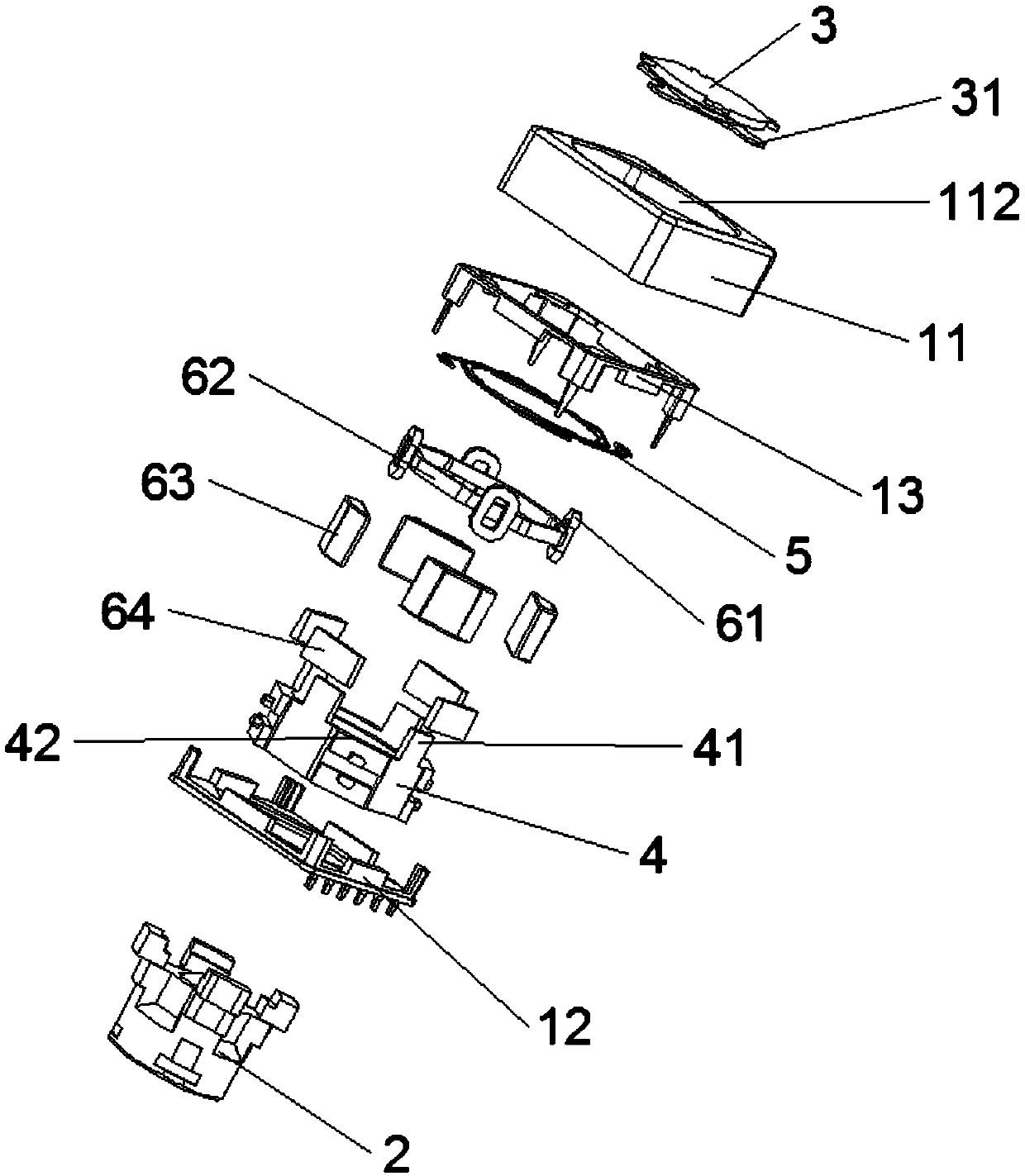
[0029] The motor of the driving liquid lens 3 of the present embodiment, refer to figure 1 As shown, it includes a seat body, a bracket 31 , a carrier 4 , a driving assembly and a second reset member 5 .

[0030] The base body is used for fixing and installing the first lens 2 and the liquid lens 3 that are distributed along the optical axis and arranged correspondingly. It includes a lower cover 12, and an upper cover 11 fixedly connected with the lower cover 12, the upper cover 11 has an accommodating cavity for setting the carrier 4, the first lens 2 and the drive assembly, and a supply for The first lens 2 and the carrier 4 protrude from the cavity opening of the accommodating cavity. In this embodiment, the cavity opening is a through hole 112 adapted to the shapes of the liquid lens 3 , the first lens 2 and the carrier 4 . In order to prevent the magnetic induction leakage in the driving assembly from affecting other parts outside the base, such as other parts on the mobi...

Embodiment 2

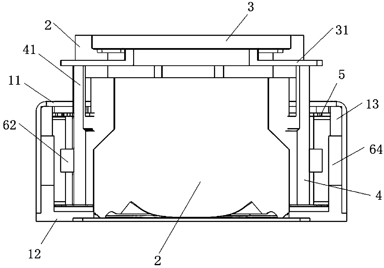
[0042] The lens group of this embodiment includes the motor for driving the liquid lens 3 in the first embodiment, the first lens 2 and the liquid lens 3 .

[0043] The first lens 2 is fixedly mounted on the lower cover 12 and is located in the receiving cavity, and is an optical lens. The carrier 4 is sleeved on the outside of the first lens 2 .

[0044] The liquid lens 3 includes a lens body, a movable plate and liquid arranged in the lens body. The movable plate moves relative to the lens body to adjust the shape of the liquid, and then adjust the curvature of the liquid lens 3 . The lens body is fixedly installed on the first lens 2 , and the first lens 2 is fixedly installed on the lower cover 12 , that is, the liquid lens 3 is installed on the base through the first lens 2 . The first lens 2 and the liquid lens 3 are distributed along the optical axis and arranged correspondingly, the distance between the first lens 2 and the liquid lens 3 is fixed, that is, the focal le...


PUM


Abstract

The invention relates to a driving device, and particularly relates to a motor and a lens group for driving a liquid lens. The motor comprises a base, a carrier, a drive assembly, and a first reset component. The drive assembly comprises a rotor disposed on the carrier, and a stator disposed on the base. The stator drives the rotor to move up and down along an optical axis and/or deflect around the optical axis. The first reset component is disposed on the liquid lens and abuts against the carrier when the carrier moves to provide a reset force for the carrier to return to an initial position.The rotor comprises a first set of coils and a second set of coils. The stator comprises a first set of magnets corresponding to the first set of coils and a second set of magnets corresponding to the second set of coils. A force deviating from the optical axis direction is generated when the first group of coils is energized, so that the carrier moves away from the optical axis direction. A force parallel to the optical axis is generated when the second set of coils is energized, so that the carrier moves in the optical axis direction. The first reset component is driven to move relative tothe liquid lens when the carrier moves, and curvature of the liquid lens is adjusted.

Description

technical field [0001] The invention relates to a driving device, in particular to a motor and a lens group for driving a liquid lens. Background technique [0002] The mobile phone camera is an important part of the mobile phone. Consumers have higher and higher requirements for the functions of the mobile phone camera such as auto focus and optical image stabilization when using the mobile phone. For the beauty and convenience of the mobile phone, the size of the mobile phone camera is also required to be smaller and smaller. . The liquid lens mainly changes the curvature of the interface of the liquid body by applying a voltage to the chamber containing the liquid. The liquid lens can achieve ultra-close focusing without causing a decrease in optical resolution when performing optical anti-shake compensation , and light in weight, suitable for miniaturized imaging devices, and more and more used in mobile phone cameras in recent years. The driving of the mobile phone le...

Claims


Application Information

Patent Timeline
Patent Type & Authority Applications(China)
IPC IPC(8): G02B26/00G03B13/36G02B7/09G03B5/00G03B30/00
CPCG02B7/09G02B26/004G03B5/00G03B13/36
Inventor 王彬洪航庆刘志远
Owner DONGGUAN PRECISION PHOTONICS LTD
Why Eureka
Try Eureka