Curvature-adjustable abrasive-belt grinding wheel

An abrasive belt and grinding wheel technology, applied in the field of machinery, can solve the problems of large occupied space, small room for transformation, low work efficiency, etc., and achieve the effects of precise adjustment, small occupied volume and simple structure

Pending Publication Date: 2018-02-09
杭州天宏智能科技有限公司
View PDF13 Cites 0 Cited by
  • Summary
  • Abstract
  • Description
  • Claims
  • Application Information

AI Technical Summary

Problems solved by technology

However, there are often multiple curved surfaces that need to be polished on the current workpiece, and the parameters such as the curvature of each curved surface are not the same. The belt cannot be polished effectively. If other polishing wheels are removed and replaced, not only the operation is inconvenient, but also the polishing efficiency is low
China Patent Network has announced a polishing wheel conversion mechanism for abrasive belt grinding and polishing machines [Application No.: 201310277803.7], which adopts a plurality of polishing wheels with different radii to be arranged in a circle, and is connected with a connecting frame. At places with different curvatures, the connecting frame is rotated The polishing wheels of different diameters are pressed against the abrasive belt for polishing, which solves the problems of inconvenient operation and low work efficiency when the existing grinding and polishing machines are used to polish surfaces with different curvatures
But there are also some problems: 1. The diameter of the polishing wheel is fixed in advance, and there is little room for change; 2. It needs to be repositioned after each change; 3. It takes up a lot of space. Enough space for the conversion mechanism to rotate

Method used


Image

  • Curvature-adjustable abrasive-belt grinding wheel
  • Curvature-adjustable abrasive-belt grinding wheel

Examples


Embodiment Construction

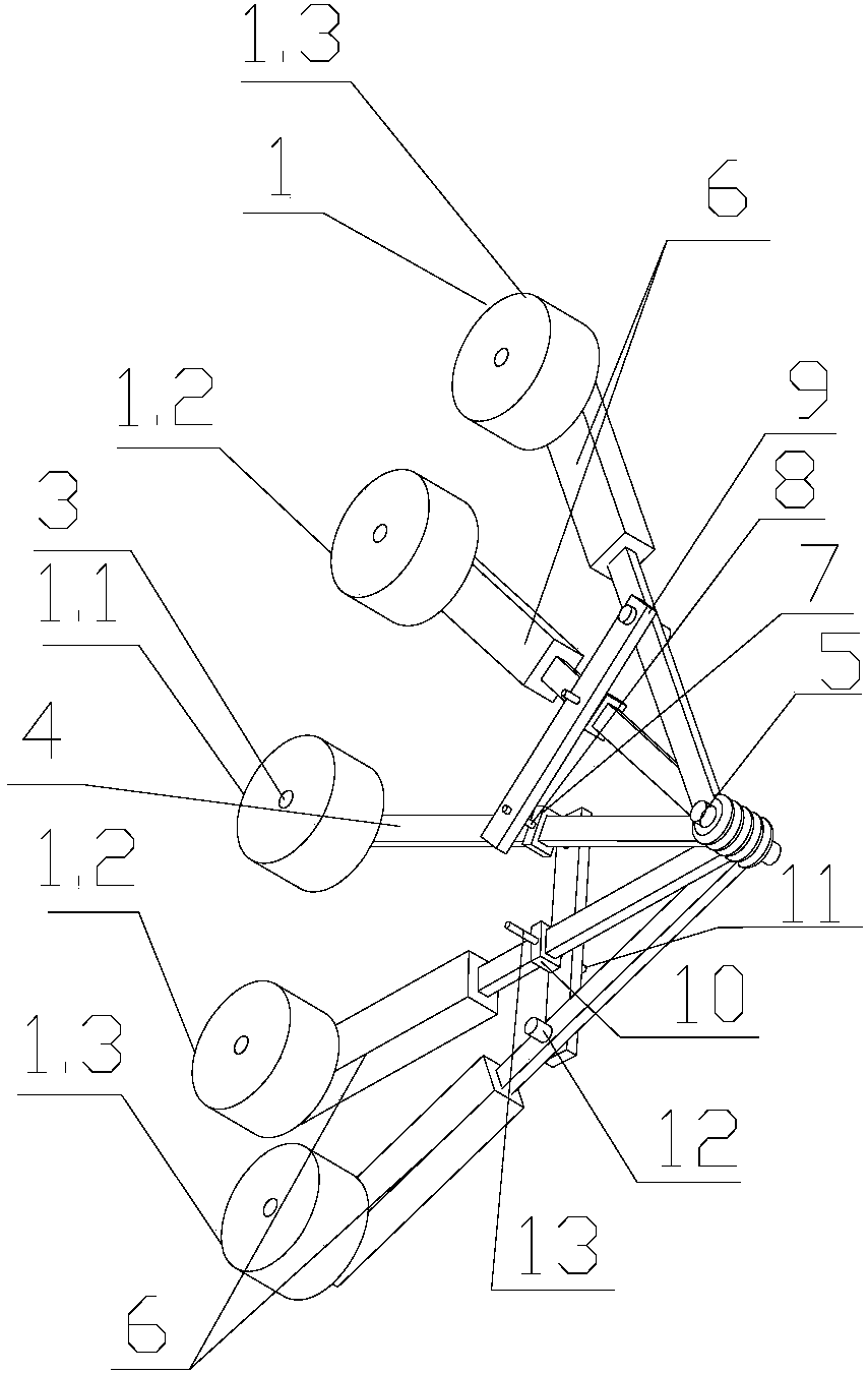
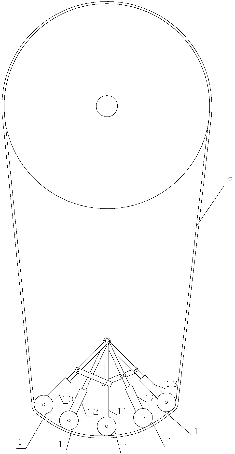
[0012] The following are specific embodiments of the present invention and in conjunction with the accompanying drawings, the technical solutions of the present invention are further described, but the present invention is not limited to the embodiments. An abrasive belt grinding wheel conversion mechanism with adjustable curvature is arranged on the inner side of the abrasive belt 2 in the polishing machine, and is characterized in that: it includes a polishing wheel 1, and the polishing wheel 1 is used to abut against the back of the abrasive belt 2 and to be positioned. The polishing wheel is divided into a main polishing wheel 1.1, two No. 1 polishing wheels 1.2 and two No. 2 polishing wheels 1.3, the No. 1 polishing wheel 1.2 is located on both sides of the main polishing wheel 1.1, and the No. 2 polishing wheel 1.3 is located Both sides of No. 1 polishing wheel 1.2, described main polishing wheel 1.1 is installed on the square main bar 4 by polishing wheel shaft 3, and th...


PUM


Abstract

The invention provides a curvature-adjustable abrasive-belt grinding wheel conversion mechanism which is arranged on the inner side of an abrasive belt in a polishing machine. The curvature-adjustableabrasive-belt grinding wheel conversion mechanism is characterized by comprising polishing wheels, wherein the polishing wheels are used for being propped against the reverse side of the abrasive belt and positioning, and comprise a main polishing wheel, two No.1 polishing wheels and two No.2 polishing wheels; the No.1 polishing wheels are positioned on two sides of the main polishing wheels; theNo.2 polishing wheels are positioned on two corresponding sides of the No.1 polishing wheels; the main polishing wheel is mounted on a square main rod through one corresponding polishing wheel axle;the other end of the main rod is connected onto a fixing shaft and can rotate along the fixing shaft; the No.1 polishing wheels and the No.2 polishing wheels are mounted at the tails of electric cylinders through the other polishing wheel axles; push rods of the electric cylinders are connected onto the fixing shaft; the electric cylinder can rotate around the fixing shaft; the main rod is sleevedby a square sliding block I; and connecting rods which can rotate on the square sliding block I around pin shafts I are mounted on the inner and outer sides of the square sliding block I through thepin shafts I.

Description

technical field [0001] The invention belongs to the technical field of machinery, in particular to an abrasive belt grinding and polishing machine, in particular to an abrasive belt grinding wheel conversion mechanism with adjustable curvature. Background technique [0002] Polishing refers to the use of mechanical, chemical or electrochemical action to reduce the surface roughness of the workpiece to obtain a bright and smooth surface. It is a modification process on the surface of the workpiece by using polishing tools and abrasive particles or other polishing media. Among them, the abrasive belt is a commonly used polishing tool, which can be elastically ground and has the functions of grinding, grinding and polishing. Compared with the grinding and polishing machine directly through the polishing wheel, the processing process is safer, the noise and dust generated are smaller, the quality of the workpiece surface after processing is high, and the application range is wi...

Claims


Application Information

Patent Timeline
Patent Type & Authority Applications(China)
IPC IPC(8): B24B21/18
CPCB24B21/18
Inventor 魏燕定沈佳魏仕槚张义强
Owner 杭州天宏智能科技有限公司
Why Eureka
Try Eureka