A driving method and equipment of a fingerprint identification device
A technology of fingerprint identification and driving method, which is applied in the directions of character and pattern recognition, acquisition/organization of fingerprints/palmprints, instruments, etc., and can solve the problems of reducing the effect of fingerprint recognition and inaccurate fingerprints
- Summary
- Abstract
- Description
- Claims
- Application Information
AI Technical Summary
Problems solved by technology
Method used
Image
Examples
Embodiment 1
[0115] During specific implementation, the fingerprint entry stage can have multiple fingerprint collection cycles. Wherein, the number of fingerprint collection cycles can be designed and determined according to the actual application environment, and is not limited here.
[0116] In the embodiment of the present invention, the same photosensitive element receives the light in the afterimage area and the light in the image area at least at least a preset afterimage elimination period, which may specifically include:
[0117] Control the point light sources of the same light-emitting sequence in two adjacent fingerprint collection periods to emit light at least at a preset time interval for afterimage elimination, so that the same photosensitive element receives the light in the afterimage area and the light in the image area in two adjacent fingerprint collection periods. There is a condition that there is at least a preset afterimage removal duration between them.
[0118] In...
Embodiment 2
[0182] The structural schematic diagram of the display panel corresponding to this embodiment is as follows Figure 7a and Figure 16 As shown, it is modified for the implementation of the fingerprint collection period in the first embodiment. The following only describes the differences between this embodiment and the first embodiment, and the similarities will not be repeated here.
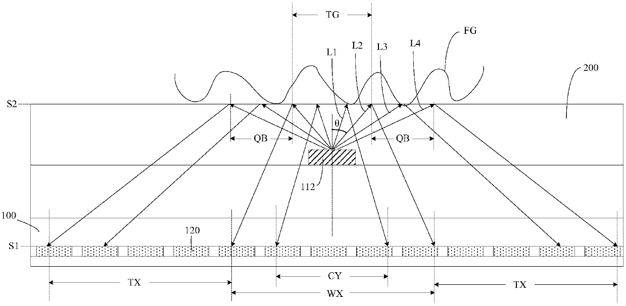
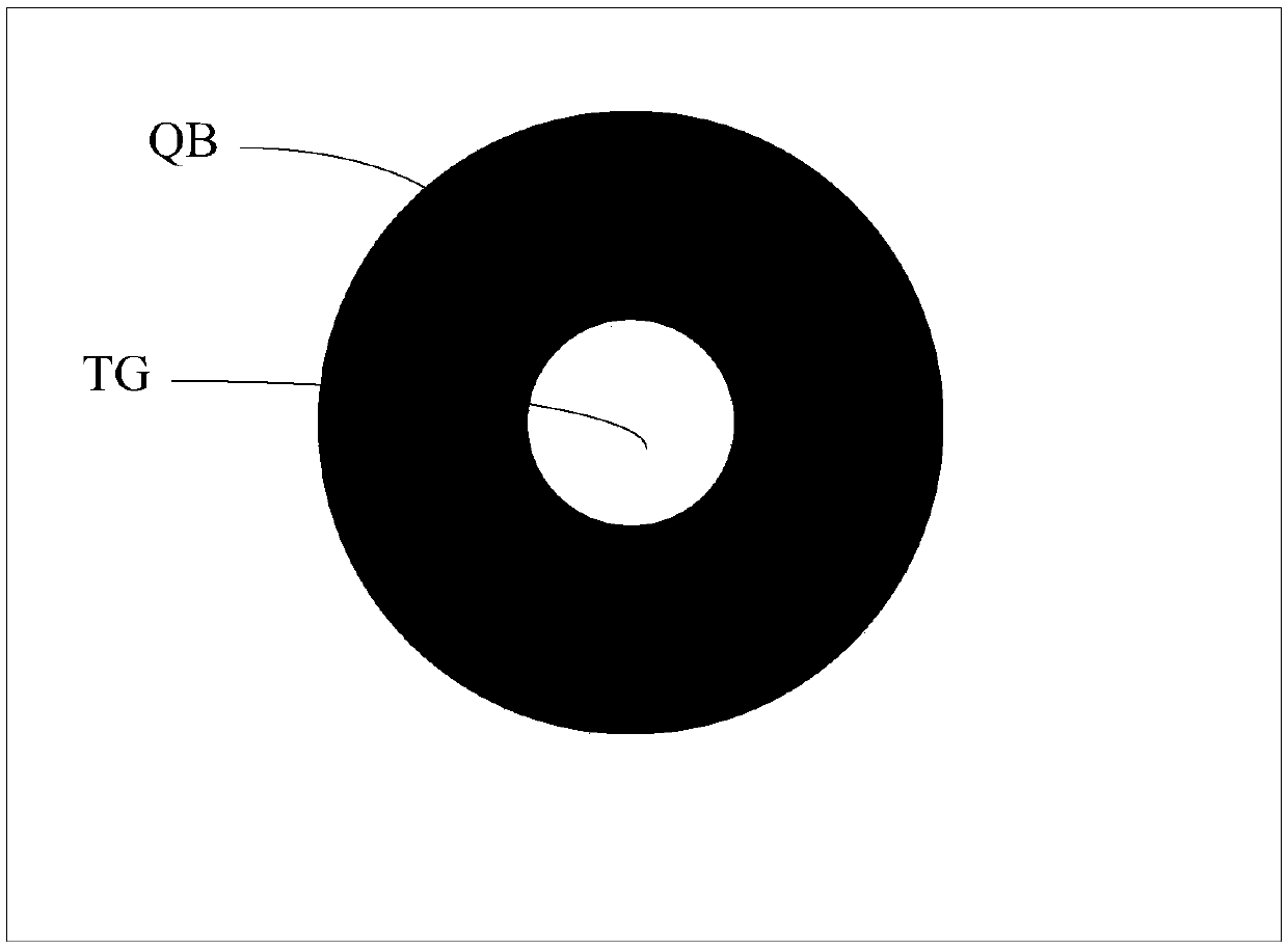
[0183] During specific implementation, in the embodiment of the present invention, the invalid area corresponding to each point light source that emits light in the nth fingerprint collection frame of the next fingerprint collection cycle can be made to cover the nth fingerprint collection frame of the previous fingerprint collection cycle The afterimage area corresponding to each point light source that emits light. In this way, the influence of the afterimage area on the accuracy of the collected fingerprints can be further avoided.
[0184] Taking the fingerprint collection cycle including...
Embodiment 3
[0186] The structural schematic diagram of the display panel corresponding to this embodiment is as follows Figure 17 As shown, it is modified for the implementation of the fingerprint identification period in the first embodiment. The following only describes the differences between this embodiment and the first embodiment, and the similarities will not be repeated here.
[0187] During specific implementation, in the embodiment of the present invention, the fingerprint recognition period may be divided into at least two consecutive fingerprint recognition frames. Wherein, two adjacent fingerprint identification frames are used as an identification frame group, and at least two continuous fingerprint identification frames are divided into continuous X identification frame groups; wherein, in the same identification frame group, the next fingerprint identification frame The invalid area corresponding to the luminous point light source covers the afterimage area corresponding...
PUM
 Abstract
Description
Claims
Application Information
 - R&D
- Intellectual Property
- Life Sciences
- Materials
- Tech Scout
- Unparalleled Data Quality
- Higher Quality Content
- 60% Fewer Hallucinations
Browse by: Latest US Patents, China's latest patents, Technical Efficacy Thesaurus, Application Domain, Technology Topic, Popular Technical Reports.
© 2025 PatSnap. All rights reserved.Legal|Privacy policy|Modern Slavery Act Transparency Statement|Sitemap|About US| Contact US: help@patsnap.com


