coil device

A coil device and winding technology, applied in the direction of transformer/inductor coil/winding/connection, circuit, electrical components, etc., can solve the problems of blockage, difficulty in increasing the number of windings, poor heat dissipation, etc.

Active Publication Date: 2021-06-22
TDK CORPARATION
View PDF8 Cites 0 Cited by
  • Summary
  • Abstract
  • Description
  • Claims
  • Application Information

AI Technical Summary

Problems solved by technology

However, in this transformer, since a flat coil is used, there is a technical problem that it is difficult to increase the number of windings
In addition, in order to make the center tap, the plate lead part of the plate coil blocks the opening of the frame, so there is also a technical problem of poor heat dissipation.

Method used


Image

  • coil device
  • coil device
  • coil device

Examples


Embodiment Construction

[0076] Hereinafter, the present invention will be described based on the embodiments shown in the drawings.

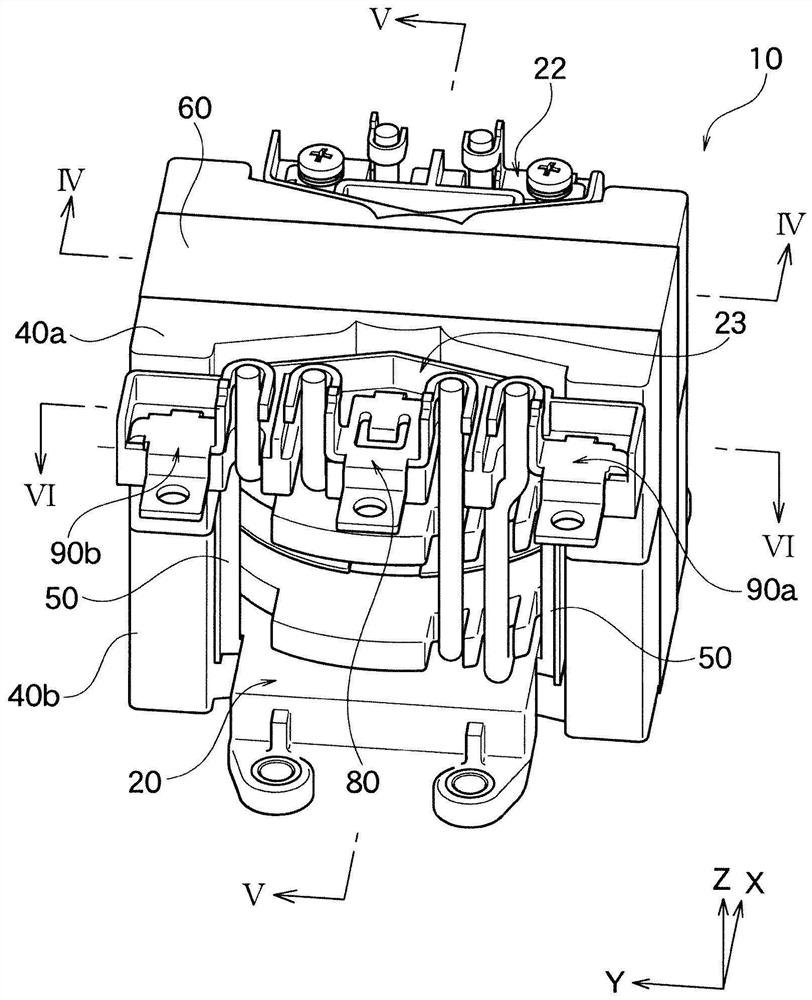
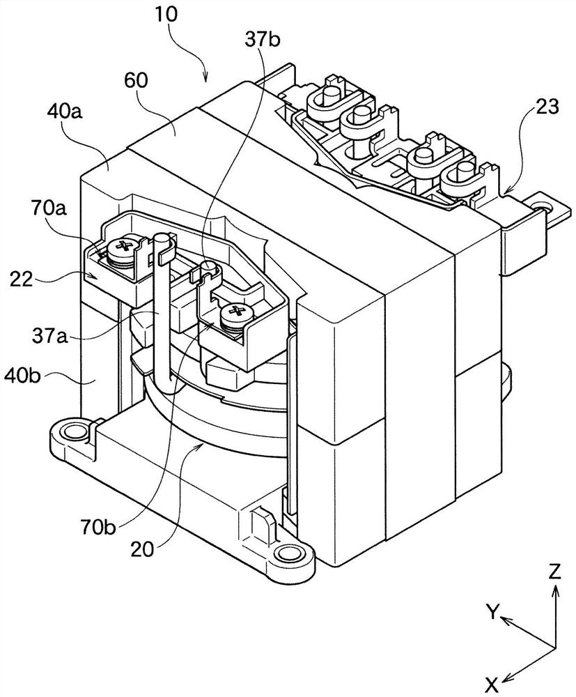
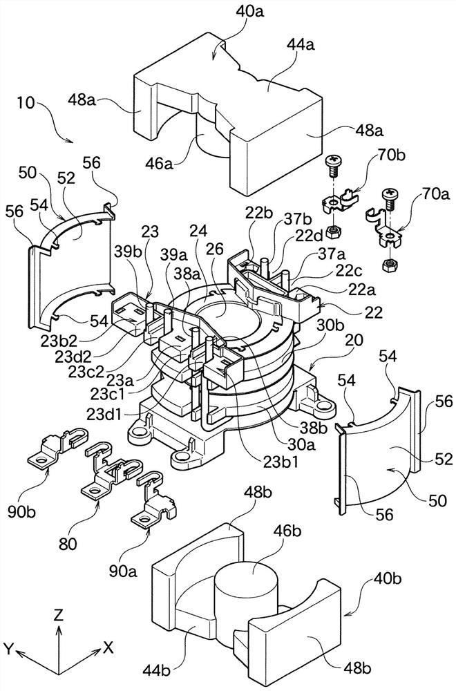
[0077] as Figure 1A as well as Figure 1B The shown transformer 10 of the coil device according to the present embodiment is used, for example, as a leaky transformer or the like for a seated object such as an automobile or the like. This transformer 10 has a skeleton 20 , magnetic cores 40 a , 40 b , a cover 50 , and a tape member 60 .

[0078] Such as figure 2 As shown, the frame 20 has a frame body 24 , and a first terminal block 22 and a second terminal block 23 integrally formed on the upper part in the Z-axis direction at both ends of the frame body 24 in the X-axis direction. On the first terminal base 22, terminal mounting portions 22a and 22b are formed at both ends in the Y-axis direction, and the first terminal 70a and the second terminal 70b are attached to these portions. The first winding wire 37 described later ( Figure 3A ), that is, a pair of fi...


PUM


Abstract

The present invention provides a coil device that can easily stabilize leakage characteristics, can easily form a center tap, can further easily control the number of windings, and exhibits excellent heat dissipation. The skeleton (20) has a first winding portion (34a, 34b) around which the first winding (37) is wound, a second winding portion (35) around which the second winding (38) is wound, a third winding The third winding part (36) where the wire (39) is wound. The first winding part (34a, 34b) is arranged between the second winding part (35) and the third winding part (36) along the axial direction of the skeleton (20), and the second winding (38) One common lead portion (38a) and one common lead portion (39a) of the third winding (39) are connected via a common terminal (80).

Description

technical field [0001] The present invention relates to a coil device such as a transformer used as a leakage transformer or the like, for example. Background technique [0002] For example, in the transformer shown in the following patent document 1, the structure which winds the winding wire for a secondary winding halfway around a terminal pin as an intermediate tap is proposed. However, in this structure, when the wire diameter of the winding wire which comprises a secondary winding is thick, it becomes difficult to wind around a terminal pin, and it becomes difficult to use a terminal pin as a center tap. In addition, in conventional transformers, it is difficult to stabilize leakage characteristics. [0003] In addition, as shown in Patent Document 2, there is also known a transformer in which a primary winding is sandwiched between planar coils. However, in this transformer, since a flat coil is used, there is a technical problem that it is difficult to increase the...

Claims


Application Information

Patent Timeline
Patent Type & Authority Patents(China)
IPC IPC(8): H01F27/29H01F27/26H01F27/30
CPCH01F27/29H01F27/306H01F27/2828H01F27/2876H01F27/34
Inventor 石桥和纪熊谷胜
Owner TDK CORPARATION
Why Eureka
Try Eureka