Energy storage container

A container and energy storage technology, applied in electrical components, electrochemical generators, fire rescue, etc., can solve the problems of reducing the utilization rate of box space, inconvenient operation, and unfavorable personal safety of operators

Inactive Publication Date: 2019-04-05
上海融政能源科技有限公司
View PDF9 Cites 8 Cited by
  • Summary
  • Abstract
  • Description
  • Claims
  • Application Information

AI Technical Summary

Problems solved by technology

[0003] However, the existing energy storage containers have the following problems: 1) The energy storage containers are open at both ends, the batteries are installed on both sides of the container, and there is a walkway in the middle. The installation, commissioning and daily maintenance of the batteries require operators to enter the container. It is not only inconvenient to operate, but also unfavorable to the personal safety of operators and prone to safety accidents. In addition, the middle aisle occupies the space in the box, which reduces the utilization rate of the box space; 2) Adopt The box wall-mounted air conditioner, the installation position of the air conditioner is protruding outwards, and it needs to be removed during shipping, which is time-consuming and laborious; 3) The horizontal fire protection system takes up a lot of space, and the direction of the fire spray is fixed, the spray is uneven when extinguishing the fire, and the fire extinguishing effect is poor ;4) During the production, testing and final assembly of the battery pack, the battery pack needs to be installed repeatedly, which is time-consuming and laborious, and the battery pack is easily damaged, which may easily cause safety accidents such as explosion of the energy storage battery
[0004] Therefore, how to solve the problems of inconvenient installation and debugging of energy storage container batteries, which are not conducive to the personal safety of operators, etc., is a technical problem that those skilled in the art need to solve at present.

Method used


Image

  • Energy storage container
  • Energy storage container
  • Energy storage container

Examples


Embodiment Construction

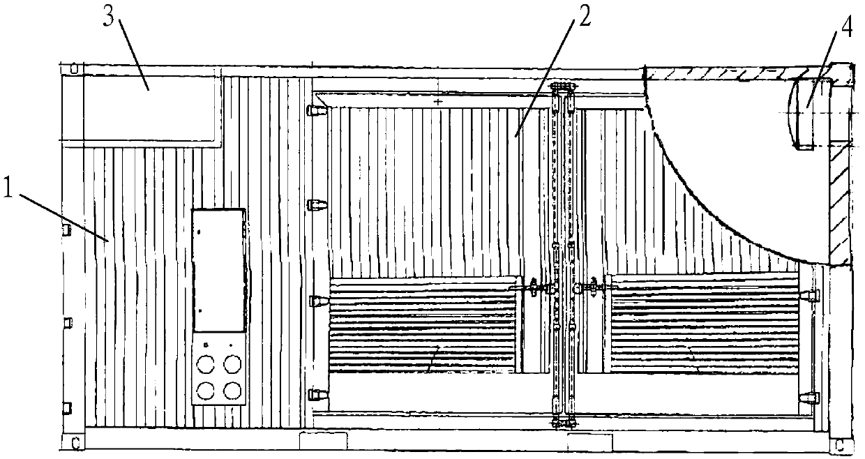
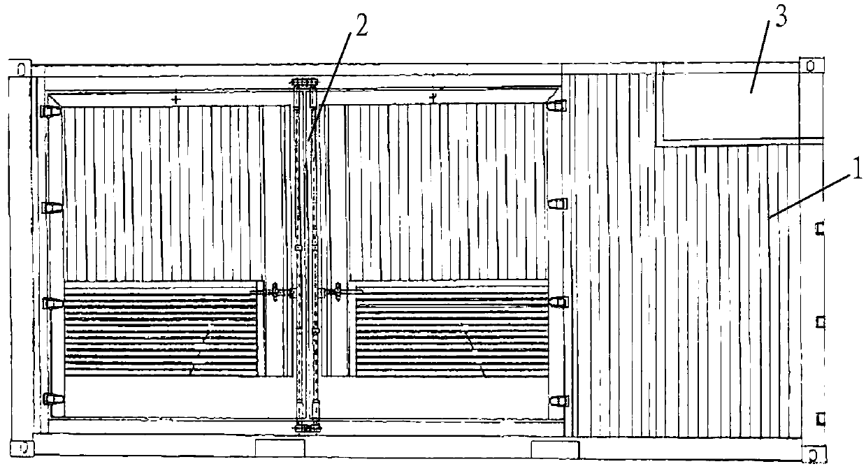
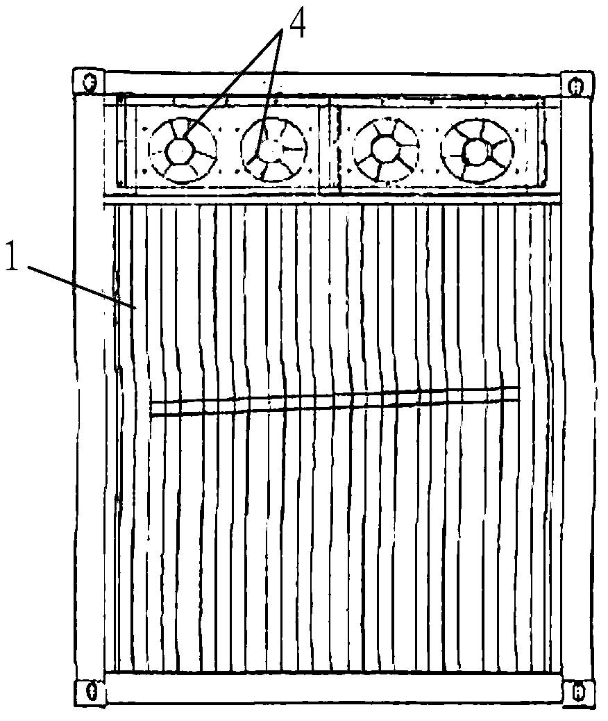
[0024] The core of the present invention is to provide an energy storage container, which adopts a structure with double doors on both sides, so that the operator can complete the installation and debugging of the energy storage battery outside the box, which is convenient to operate and has high safety.

[0025] In order to enable those skilled in the art to better understand the solution of the present invention, the present invention will be further described in detail below in conjunction with the accompanying drawings and specific embodiments.

[0026] Please refer to Figure 1 to Figure 4 , figure 1 It is a structural schematic diagram of a specific embodiment of the energy storage container provided by the present invention; figure 2 A rear view of a specific embodiment of the energy storage container provided by the present invention; image 3 It is the right view of a specific embodiment of the energy storage container provided by the present invention; Figure 4 ...


PUM


Abstract

The invention discloses an energy storage container comprising a box body, a storage rack disposed in the box body and an energy storage battery placed on the storage rack. Two sides of the box body are provided with double-door bodies for facilitating the installation and debugging of the energy storage battery. The double-door bodies are arranged on two sides of the energy storage container, sothat the double-door bodies are opened in battery installation, debugging or daily maintenance, an operator can perform various operations at the outside of the box body without entering a charged area in the box body, the operation is convenient, doors on two sides of the box body meets the requirements of the safety specification UL9540 and international safety specifications, personal injury and other possible safety accidents can be avoided, and the safety is high. In addition, since the operator can complete various operations outside the box body, a walkway in the box body is not needed,the capacity of the energy storage battery in the box body can be increased, and the space utilization of the box body is improved.

Description

technical field [0001] The invention relates to the technical field of mobile energy storage equipment, in particular to an energy storage container. Background technique [0002] Energy storage is an important part and key technology of smart grids, renewable energy systems, and energy Internet. With the outbreak of large-scale energy storage market applications and the large-scale development of micro-grids, mobile energy storage containers are increasingly becoming a part of modern power systems. An indispensable and important part, the mobile energy storage container carries the battery pack and its auxiliary equipment for storing electric energy through the container, so as to facilitate transportation to the place where it needs to be used. The battery pack and auxiliary equipment in the container need to be arranged reasonably. Reliable fixation, easy maintenance, and good ventilation and heat dissipation. [0003] However, the existing energy storage containers have...

Claims


Application Information

Patent Timeline
Patent Type & Authority Applications(China)
IPC IPC(8): H01M2/10H01M10/613H01M10/627H01M10/6563H01M10/663A62C3/16H01M50/204
CPCA62C3/16H01M10/613H01M10/627H01M10/6563H01M10/663H01M50/20Y02E60/10
Inventor 李靖滨
Owner 上海融政能源科技有限公司
Why Eureka
Try Eureka