[0022] The present invention is further described in conjunction with the following examples.
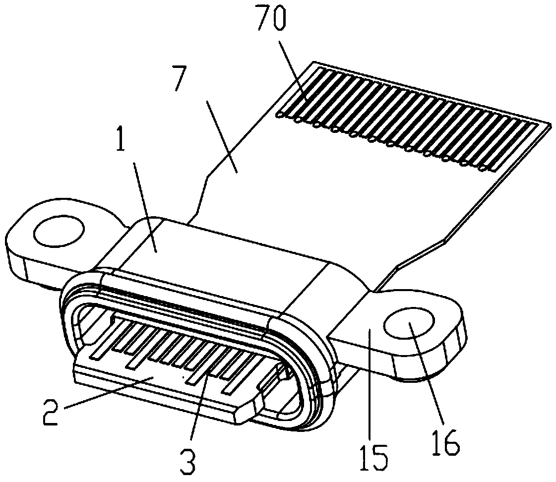
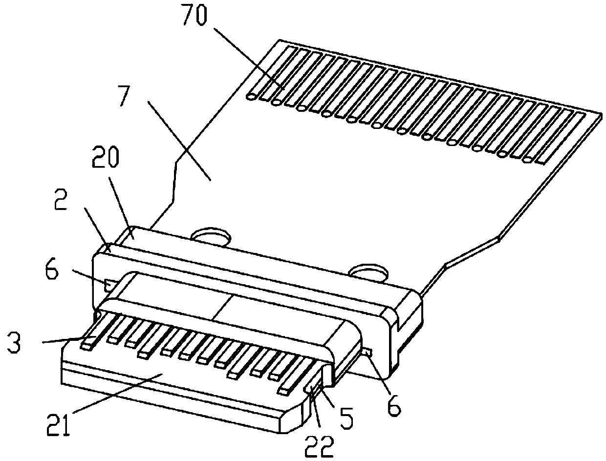
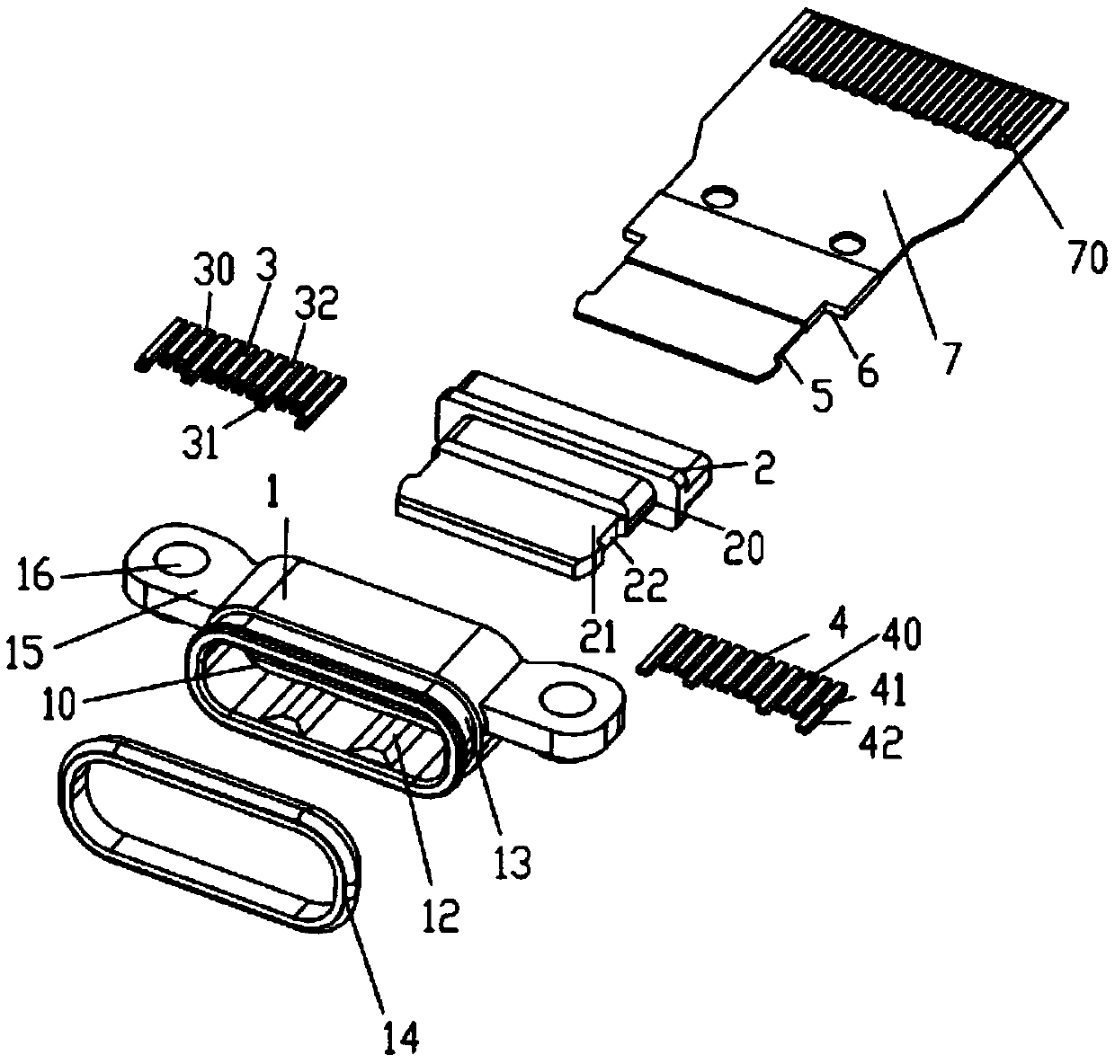
[0023] A specific embodiment of an electrical connector socket of the present invention, such as figure 1 , image 3 As shown, the electrical connector socket is used for plugging with an electrical connector plug. The electrical connector socket includes a shell 1 and an insulating body 2. The shell 1 includes a receiving groove 10, and the insulating body 2 is arranged in the receiving groove 10. The insulating body 2 includes a base 20 and a tongue plate 21. The tongue plate 21 is formed by extending forward from the front end of the base 20. Two second grounding points 6 are also provided on the front end surface of the base 20. The tongue plate 21 is located at two Between the second grounding points 6 , when the electrical connector socket and the electrical connector plug are inserted, the two second grounding points 6 are connected to the LATCH of the electrical connector plug and grounded. Tongue plate 21 includes an upper surface and a lower surface.
[0024] like figure 1 , 3 As shown, the electrical connector socket includes two rows of terminals, respectively the first row of terminals 3 and the second row of terminals 4, the first row of terminals 3 and the second row of terminals 4 are arranged up and down, and are connected to the tongue plate 21 of the insulating body 2 Integral molding, the first row of terminals 3 is embedded in the upper surface of the tongue plate 21, the second row of terminals 4 is embedded in the lower surface of the tongue plate 21, the first row of terminals 3 includes a plurality of first terminals 30, and the plurality of first terminals 30 include signal Terminals, power terminals, each first terminal 30 is provided with a first main body portion 31 and a first contact portion 32, the first contact portion 32 extends upward from the first main body portion 31, and the first contact portion 32 is used to communicate with The terminals in the electrical connector plug are in contact, and the first contact portion 32 protrudes from the upper surface of the tongue plate 21; the second row of terminals 4 includes a plurality of second terminals 40, and the plurality of second terminals 40 includes signal terminals and power terminals. A second terminal 40 is provided with a second body part 41 and a second contact part 42, the second contact part 42 extends upward from the second body part 41, and the second contact part 42 is used for connecting with the electrical connector plug The terminal contacts, and the second contact portion 42 protrudes from the lower surface of the tongue plate 21 . The left and right sides of the tongue plate 21 are provided with grooves 22, the grooves 22 are formed by inward depressions from the side walls of the tongue plate 21, the grooves 22 on the left and right sides are used to engage with the electrical connector plug, and the electrical connector The socket and the electrical connector plug are clamped together. The electrical connection socket also includes a flexible circuit board 7 (commonly known as FPC). The connection end of the flexible circuit board 7 is connected to the electrical connector socket. The point 5 is located in the groove 22. When the electrical connection socket is plugged with the electrical connector plug, the outer side of the first grounding point 5 conducts with the iron shell of the electrical connection plug. The second ground point 6 is also provided on the flexible circuit board 7 .
[0025] like figure 2 and image 3 As shown, gold fingers 70 are provided on the upper surface and the lower surface of the free end of the flexible circuit board 7, and the connection end of the flexible circuit board 7 is embedded in the tongue plate 21, and the connection end of the flexible circuit board 7 is located at Between the first row of terminals 3 and the second row of terminals 4, the first body part 31 and the second body part 41 are respectively welded on the upper surface and the lower surface of the connecting end of the flexible circuit board 7, so that the first row of terminals 3, the second row of terminals The two rows of terminals 4 are electrically connected to the flexible circuit board 7, and the flexible circuit board 7 is used to replace the traditional USB TYPE C tongue, and there is no need to set a separate shield between the upper and lower rows of terminals like the traditional USB TYPE C connector The signal is shielded, and the flexible circuit board 7 also plays the role of shielding the signal crosstalk between the upper and lower terminals while electrically connecting the terminals. The structure is simple, and the transmission and wiring are more convenient, the signal integrity performance is more superior, and the assembly and use are convenient. Further, the electrical connector socket in this embodiment involves less structures, and the overall structure is small in volume. The first row of terminals 3, the second row of terminals 4, the tongue plate 21 and the connecting end of the flexible circuit board 7 are integrally formed, and there is no need for multiple steps of assembly. The integral molding makes the manufacturing process of the overall structure simple and the cost is reduced. .
[0026] The inner wall of the housing 1 is provided with a plugging convex strip 12, which is used for plugging with an electrical connection plug, and the outer wall of the front end of the casing 1 (that is, the end close to the plugging convex strip 12) is provided with an annular groove 13. The annular groove 13 surrounds a circle along the outer wall of the housing 1, and a sealing ring 14 is arranged on it. The sealing ring 14 is sleeved in the annular groove 13. The sealing ring 14 is a waterproof ring. The sealing ring 14 is integrally formed, so that The shell 1 of the electrical connector socket has good sealing and waterproof performance, and its waterproof performance can reach IPX8. The left and right sides of the housing 1 are provided with extensions 15, and each extension 15 is provided with a connection hole 16, which is threaded with the connection hole 16 by using the screw/bolt/screw passing through the connection hole 16 to connect the The electrical connection socket is fixed, and the extension part 15 is integrally formed with the casing 1, so that the waterproof performance is increased.
[0027] Finally, it should be noted that the above embodiments are only used to illustrate the technical solutions of the present invention, rather than limiting the protection scope of the present invention, although the present invention has been described in detail with reference to the preferred embodiments, those of ordinary skill in the art should understand , the technical solution of the present invention may be modified or equivalently replaced without departing from the spirit and scope of the technical solution of the present invention.