Power connector and assembly method thereof

A technology for power connectors and socket slots, which is applied to the components, connections, and assembly/disassembly of contact pieces of connection devices. The effect of taking into account the convenience of assembly and thinning requirements, improving assembly strength, and reducing the probability of false touch

Active Publication Date: 2019-04-05
GIGA COMPUTING TECHNOLOGY CO LTD
View PDF4 Cites 0 Cited by
  • Summary
  • Abstract
  • Description
  • Claims
  • Application Information

AI Technical Summary

Problems solved by technology

[0004] In view of the above problems, the present invention discloses a power connector and its assembly method, so as to solve the problem in the prior art that it is difficult to balance the ease of assembly and thinning of the power connector

Method used


Image

  • Power connector and assembly method thereof
  • Power connector and assembly method thereof
  • Power connector and assembly method thereof

Examples


Embodiment Construction

[0072] The technical solution of the present invention will be described in detail below in conjunction with the accompanying drawings and specific embodiments to further understand the purpose, solution and effect of the present invention, but it is not intended to limit the scope of protection of the appended claims of the present invention.

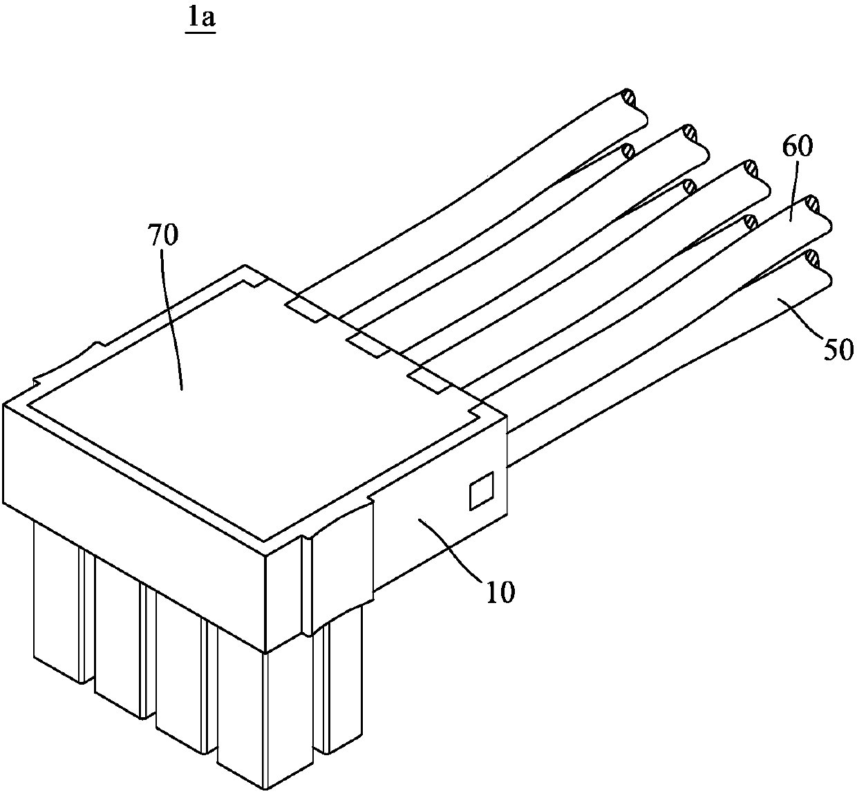
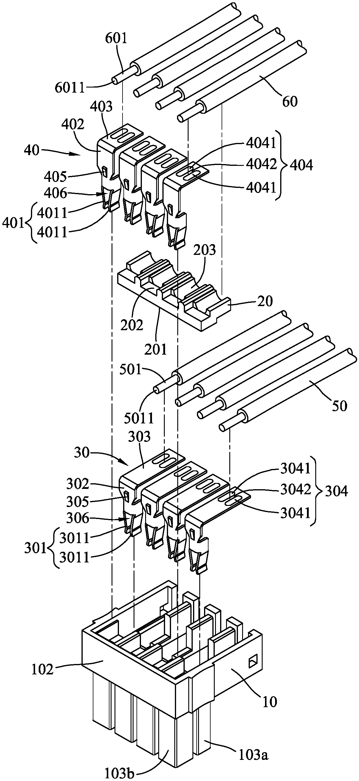
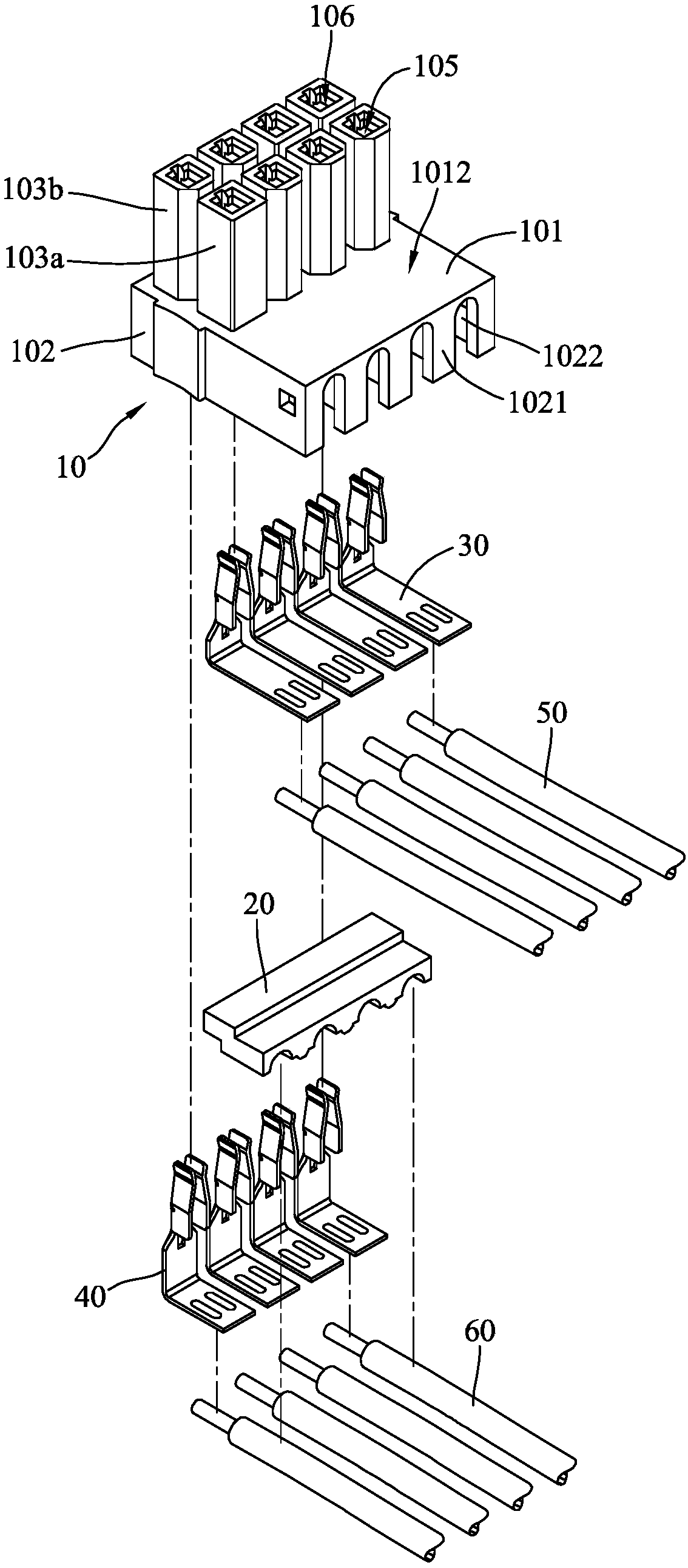
[0073] see Figure 1 to Figure 5 . figure 1 It is a three-dimensional schematic view of the power connector according to the first embodiment of the present invention. figure 2 for figure 1 An exploded view of an unfilled power connector. image 3 for figure 1An exploded view of another view of the power connector without filling. Figure 4 for figure 1 A cross-sectional schematic diagram of a power connector plugged into a mating connector. Figure 5 for figure 1 A schematic cross-sectional view of the housing of the power connector.

[0074] In this embodiment, the power connector 1a includes a housing 10, a partition 20, a ...


PUM


Abstract

The invention discloses a power connector. The power connector comprises an outer cover, partition plates, a plurality of first pins, a plurality of second pins, a plurality of first wires, a plurality of second wires and a filler, wherein an accommodating groove, a plurality of first slots and a plurality of second slots are formed in the outer cover, the first slots and the second slots are connected with the accommodating groove, the partition plates are arranged in the accommodating groove and are used for partitioning the accommodating groove into a plurality of first line slots and a plurality of second line slots, extension directions of the first slots and the second slots are respectively perpendicular to extension directions of the first line slots and the second line slots, thefirst pins and the second pins are respectively and partially arranged in the first slots and the second slots and are partially arranged in the first line slots and the second line slots, the first wires and the second wires are respectively arranged in the first line slots and the second line slots and are respectively and electrically connected with the first pins and the second pins, the filler is opposite to the material of the outer cover, and the filler is filled in the accommodating groove so as to package and block the first wires and the second wires.

Description

technical field [0001] The present invention relates to a connector and its assembly method, in particular to a power connector and its assembly method. Background technique [0002] Generally speaking, computer equipment includes servers and personal computers. Wherein, taking a server as an example, the electronic devices in the server usually transmit signals and currents through connectors with wires. However, when the connectors are serially connected to various electronic devices, the wires of the connectors are usually scattered in the server to block the heat dissipation air flow, thereby reducing the heat dissipation efficiency of the server. In addition, electronic components in a personal computer, such as a power supply, a central processing unit, and a display card, are also connected in series by wires provided with connectors. The advantage of the connector is that the wires can be quickly assembled or removed from the electronic components without tools. ...

Claims


Application Information

Patent Timeline
IPC IPC(8): H01R13/504H01R43/24
CPCH01R13/504H01R43/24H01R2201/06
Inventor 蔡东霖侯智仁陈长祥黄进权戴忠邦
Owner GIGA COMPUTING TECHNOLOGY CO LTD
Why Eureka
Try Eureka