Fixed structure for installing secondary pipe and method for installing secondary pipe

A fixed structure and piping technology, applied in cable installation devices, cable installation, electrical components, etc., can solve problems such as cutting slits and grooving, and achieve the effect of fast installation, reduction of material waste, construction period and labor saving.

Pending Publication Date: 2019-04-05
成都建工第二建筑工程有限公司
View PDF5 Cites 0 Cited by
  • Summary
  • Abstract
  • Description
  • Claims
  • Application Information

AI Technical Summary

Problems solved by technology

[0004] The main purpose of the present invention is to provide a fixed structure for installing secondary piping and a method for installing secondary piping, so as to solve the problem of cutting and picking grooves in the installation of secondary piping in the prior art

Method used


Image

  • Fixed structure for installing secondary pipe and method for installing secondary pipe
  • Fixed structure for installing secondary pipe and method for installing secondary pipe
  • Fixed structure for installing secondary pipe and method for installing secondary pipe

Examples


Embodiment 1

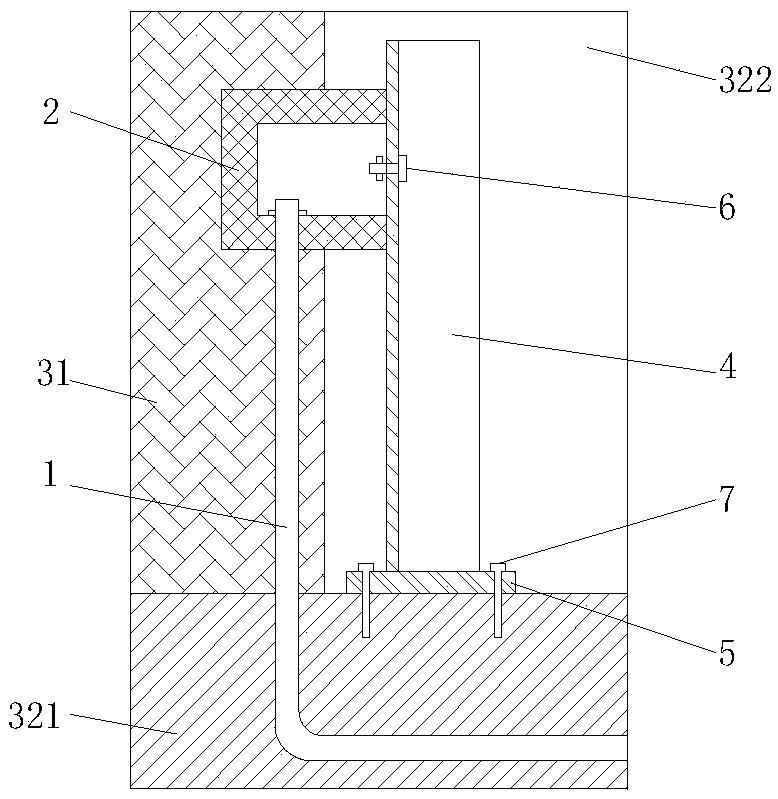
[0047] The secondary piping includes a wire pipe 1 embedded in the first wall surface 31 and a wire box 2 arranged at an end of the wire pipe 1 . Such as figure 1 The shown fixing structure for installing the secondary piping includes a support rod 4, one end of which is fastened to the junction box 2, and the other end is fastened to the built wall.

[0048] The support rod 4 is an angle steel, and the model is ∠40*4.

[0049] A screw hole 21 is provided on the wire box 2, and a first hole matching the screw hole 21 is provided on the support rod 4, and the support rod 4 and the wire box 2 are passed through by a screw 6 The screw hole 21 and the first hole realize fastening connection; as Figure 4 As shown, the wire box 2 is a type 86 wire box. There are two screw holes 21 and two first holes respectively. The diameter of the first hole is 4mm. The screw 6 is a galvanized screw 6 .

[0050] A support base 5 is provided between the support rod 4 and the second wall sur...

Embodiment 2

[0053] Compared with Embodiment 1, the difference of the fixing structure for installing the secondary piping in this embodiment is that: the second wall is the floor 322, and the support rod 4 is placed vertically at this time.

Embodiment 3

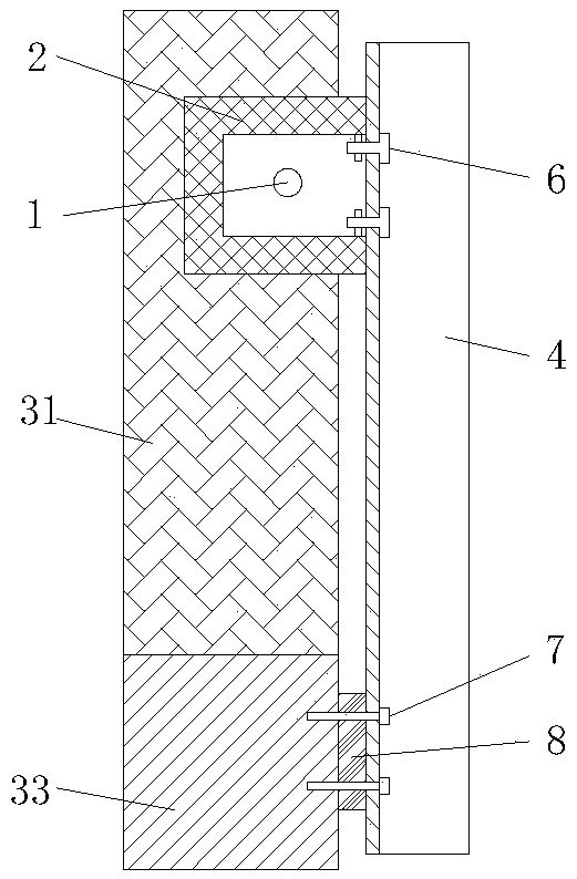
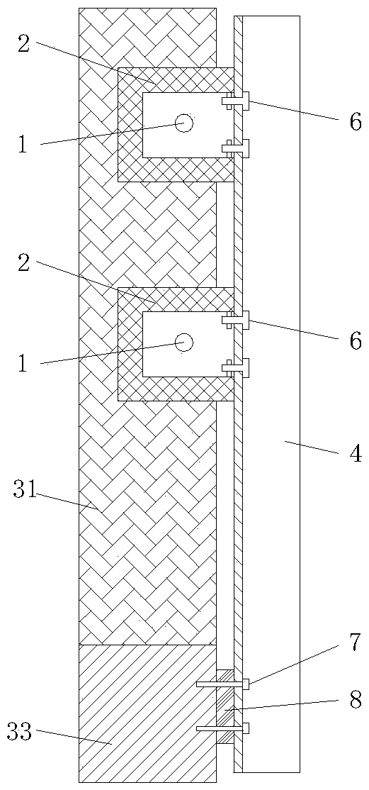
[0055] The secondary piping includes a wire pipe 1 embedded in the first wall surface 31 and a wire box 2 arranged at an end of the wire pipe 1 . Such as figure 2 The shown fixing structure for installing the secondary piping includes a support rod 4, one end of which is fastened to the junction box 2, and the other end is fastened to the built wall.

[0056] The support rod 4 is an angle steel.

[0057] A screw hole 21 is provided on the wire box 2, and a first hole matching the screw hole 21 is provided on the support rod 4, and the support rod 4 and the wire box 2 are passed through by a screw 6 The screw hole 21 and the first hole realize fastening connection; as Figure 4 As shown, the wire box 2 is a type 86 wire box. There are two screw holes 21 and two first holes respectively. The diameter of the first hole is 4mm. The screw 6 is a galvanized screw 6 .

[0058] The support rod 4 is connected with the third wall 33 by expansion screws 7; the third wall 33 is in ...


PUM


Abstract

The invention discloses a fixed structure for installing a secondary pipe and a method for installing the secondary pipe. The secondary pipe comprises a line pipe and a wire box, wherein the line pipeis buried in a first wall, and the wire box is arranged at an end part of the line pipe. The fixed structure for installing the secondary pipe comprises a support rod, wherein one end of the supportrod is fastened and connected with the wire box, and the other end of the support rod is fastened and connected with a built wall. By the fixed structure for installing the secondary pipe, primary positioning formation can be performed on the line pipe and the wire box, accurate installation of the line pipe and the wire box is ensured, the damage of construction of brick setting is effectively prevented, the brick, line pipe and wire box formation effect is good, the influence on brick appearance quality is also reduced as much as possible, groove and hole disassembly is reduced, constructionis facilitated, and the material waste is reduced; the fixed structure is low in cost and can be repeatedly used; the fixed structure can be circularly used and is convenient to install and disassembly; and therefore, the fixed structure for installing the secondary pipe is simple and is high in practicability.

Description

technical field [0001] The invention relates to the technical field of installing secondary piping in buildings, in particular to a fixing structure for installing secondary piping and a method for installing secondary piping. Background technique [0002] As construction projects become more and more perfect, the quality requirements of construction projects continue to increase, and the requirements for re-construction of line pipes and wire boxes in brick masonry are becoming more and more precise and strict, which is not a small test for our installation projects. [0003] At present, when brick masonry is used in the installation project, the wire pipes and wire boxes are wrapped in bricks after construction is completed in advance. During the wrapping period, personnel are arranged to adjust the tube boxes to ensure that all the tube boxes can be wrapped in place. However, in the brick masonry package, there will inevitably be various unavoidable situations: in the pro...

Claims


Application Information

Patent Timeline
Patent Type & Authority Applications(China)
IPC IPC(8): H02G1/00H02G1/08
CPCH02G1/00H02G1/08
Inventor 薛庆文刘刚冯家荣陈建仁王永斌林裕田泽辉王文珏文俊杰石伟尹超张敏
Owner 成都建工第二建筑工程有限公司
Why Eureka
Try Eureka