
Combined magnetic attracting type wireless charger

A technology of wireless charger and magnetic adsorption, applied in the direction of current collectors, electric vehicles, electrical components, etc., can solve the problems of inconvenient to carry, wireless charger thickness, volume increase, and inability to be used anytime, anywhere, etc.

Active Publication Date: 2019-04-05
东莞市万盈机械有限公司
View PDF5 Cites 1 Cited by
  • Summary
  • Abstract
  • Description
  • Claims
  • Application Information

AI Technical Summary

Problems solved by technology

[0004] The purpose of the present invention is to provide a combined magnetic adsorption wireless charger, which can solve the problem that there is only one set of charging coils for fast charging or ordinary charging inside the traditional wireless charger, so that the wireless charger only has fast charging or It is the function of ordinary charging. When the wireless charger needs to support the fast charging function, it is necessary to add corresponding fast charging components and coils inside the wireless charger, resulting in a corresponding increase in the thickness and volume of the entire wireless charger, which is inconvenient to carry. , and the existing wireless chargers still need to rely on an external USB charging cable to be powered on, and cannot completely get rid of the function of the charging cable, nor can it be used anytime, anywhere

Method used


Image

  • Combined magnetic attracting type wireless charger
  • Combined magnetic attracting type wireless charger
  • Combined magnetic attracting type wireless charger

Examples


Embodiment Construction

[0030] The technical solutions of the present invention will be clearly and completely described below in conjunction with the embodiments. Apparently, the described embodiments are only some of the embodiments of the present invention, not all of them. Based on the embodiments of the present invention, all other embodiments obtained by persons of ordinary skill in the art without creative efforts fall within the protection scope of the present invention.

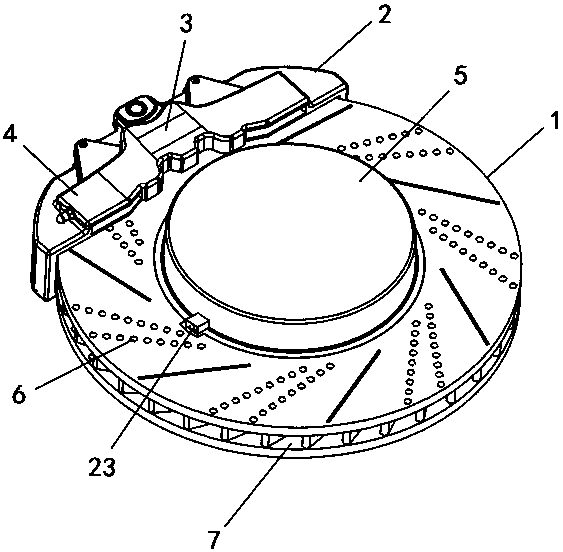
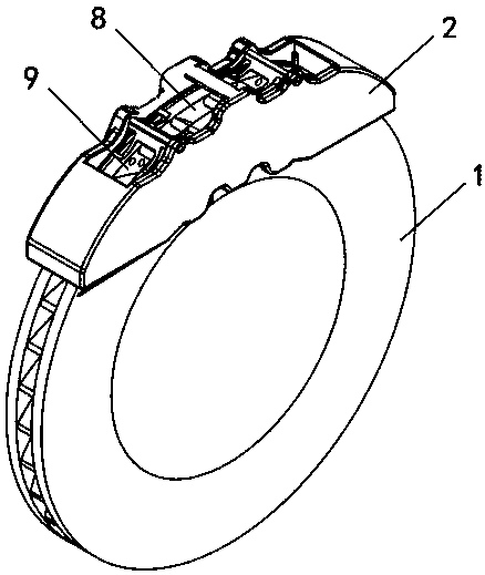
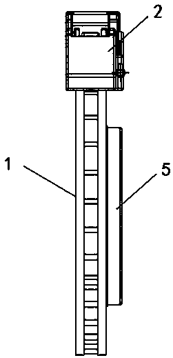
[0031] see Figure 1-7 As shown, a combined magnetic adsorption wireless charger includes a housing 1 and a charging tray 5 installed in the middle, a jacket 2 is installed on the side wall of the housing 1, and a PLC controller 3 is embedded on the top outer wall of the jacket 2 One side of the PLC controller 3 is provided with a storage battery 4 embedded in the top outer wall of the jacket 2, a wiring hole 8 is provided in the middle of the outer wall of one side of the jacket 2, and a charging hole 9 corresponding to th...


PUM


Abstract

The invention discloses a combined magnetic attracting type wireless charger. The problems that the thickness and size of the whole wireless charger are correspondingly increased and are inconvenientto carry due to the fact that only one group of charging coils for rapid charge or normal charge exists in the conventional wireless charger and the wireless charger only has the function of rapid charge or normal charge and a corresponding rapid charge component and coil are increased inside the wireless charger when the wireless charger needs to support the rapid charge function, and the existing wireless charger is adopted by virtue of electrification of the external USB (Universal Serial Bus) charge line and cannot completely get rid of the charge line and cannot be used at any time and any place can be solved. The wireless charger comprises a shell and a charging panel mounted in a middle part of the shell; a clamp sleeve is mounted on a side wall of the shell; a PLC (Programmable Logic Controller) is embedded on an outer wall of the top of the clamp sleeve; and one side of the PLC is provided with a storage battery embedded in the outer wall of the top of the clamp sleeve.

Description

technical field [0001] The invention relates to a wireless charger, in particular to a combined magnetic force adsorption wireless charger. Background technique [0002] A wireless charger refers to a charger that does not need to be connected to a terminal device that needs to be charged using a traditional charging power cord. It uses wireless charging technology to transmit electric energy by using the alternating magnetic field generated between the coils. Inductive coupling technology will become a connection A bridge for charging base stations and devices. [0003] However, the existing wireless chargers still have certain defects in use. First, because there is only one set of charging coils for fast charging or ordinary charging inside the wireless charger, the wireless charger only has fast charging or ordinary charging. function, when the wireless charger needs to support the fast charging function, it is necessary to add corresponding fast charging components and...

Claims


Application Information

Patent Timeline
IPC IPC(8): H02J7/00H02J50/10
CPCH02J7/0042H02J50/10
Inventor 余杨琴余中优
Owner 东莞市万盈机械有限公司
Learn More