
PERMANENT MAGNET ROTOR, METHOD FOR PRODUCING SAME, AND magnetization device

A permanent magnet rotor and equipment technology, applied in the direction of magnetic circuit rotating parts, manufacturing motor generators, manufacturing stator/rotor body, etc., can solve the problems of magnetic field strength limitation, some areas of magnets are not completely magnetized, etc., and achieve high The effect of magnetizing field strength

Active Publication Date: 2019-04-05
BUHLER MOTOR GMBH
View PDF10 Cites 4 Cited by
  • Summary
  • Abstract
  • Description
  • Claims
  • Application Information

AI Technical Summary

Problems solved by technology

Pre-installed permanent magnet rotors can be magnetized from the outside, but the achievable field strength is limited by saturation effects in the iron core, so that some areas of the magnet are not completely magnetized

Method used


Image

  • PERMANENT MAGNET ROTOR, METHOD FOR PRODUCING SAME, AND magnetization device
  • PERMANENT MAGNET ROTOR, METHOD FOR PRODUCING SAME, AND magnetization device
  • PERMANENT MAGNET ROTOR, METHOD FOR PRODUCING SAME, AND magnetization device

Examples


Embodiment Construction

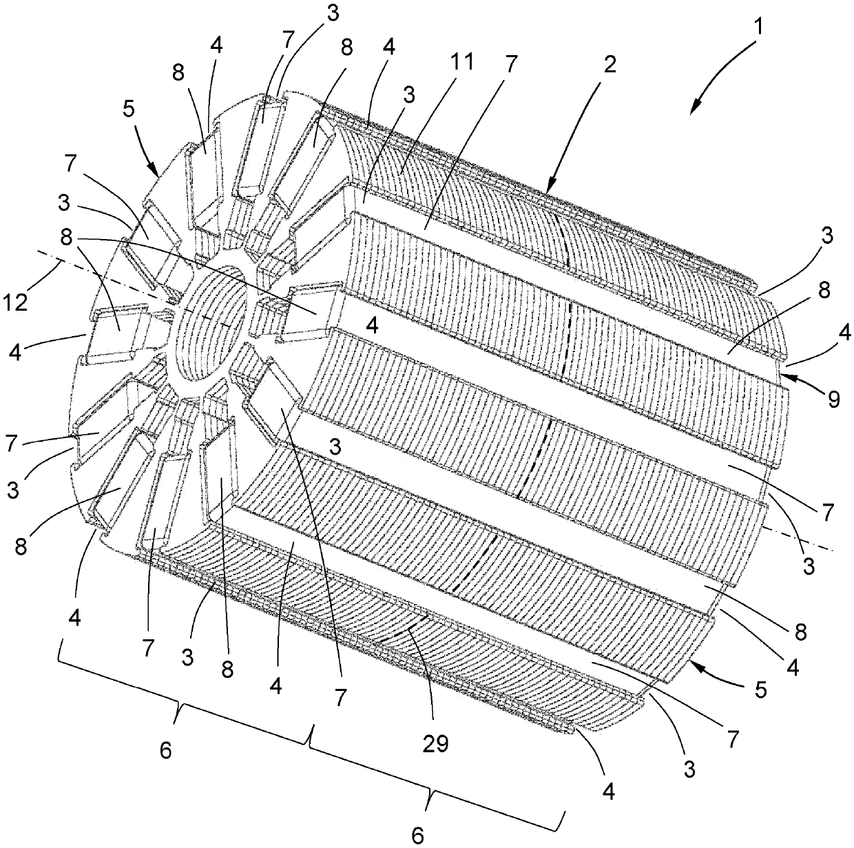
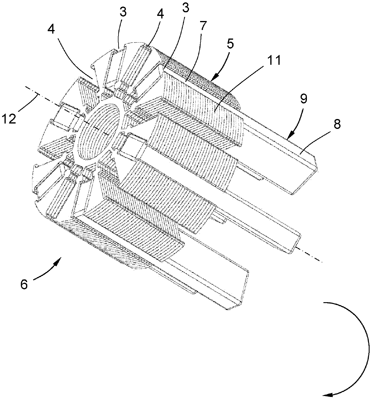
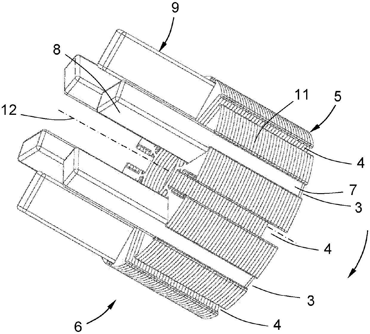
[0051] figure 1 A permanent magnet rotor 1 is shown (without rotor shaft) with a rotor axis of rotation 12 , a magnetic core 2 and permanent magnet blocks 9 mounted in magnet receptacles 3 , 4 . The magnetic core 2 is axially composed of two identical sub-cores 5 (see parting line 29 ). The permanent magnet blocks 9 are each accommodated with a first partial section 7 in the magnet receptacle 3 of one partial core 5 and with a second partial section 8 in the magnet receptacle 4 of the second partial core 5 . The first partial section 7 is mounted with an interference fit in every other magnet receptacle 3 of the two partial cores 5 and with a clearance or transition fit in the remaining magnet receptacles 4 . Each sub-core 5 and a plurality of permanent magnet blocks 9 form a rotor structural assembly 6 . exist figure 1 Twelve permanent magnet blocks 9 are shown in , wherein six permanent magnet blocks and sub-cores 5 form a rotor structure assembly 6 respectively. Two rot...


PUM


Abstract

The invention relates to a permanent magnet rotor, a method for producing the same, and a magnetization device. A permanent magnet rotor (1) with a magnetically conductive magnetic core (2), which hasa plurality of magnet retainers (3, 4) for radially arranged and essentially tangentially magnetized permanent magnet parts (9), and a method for the production thereof. With a common permanent magnet rotor, the object of the present invention is to ensure a simple installation for a low number of components to be installed, very good magnetizability, high strength of the mechanical connection ofthe permanent magnet parts in the magnet retainers, and a compact size.

Description

technical field [0001] The invention relates to a permanent magnet rotor (1) having a magnetically conductive core (2) with a plurality of magnet receptacles (3, 4) for radially arranged and substantially A tangentially magnetized permanent magnet block (9), and the invention also relates to a method for manufacturing the permanent magnet rotor. Background technique [0002] A generic permanent-magnet rotor is known, for example, from EP 3 054 466 A1, in which permanent magnet segments are accommodated magnetized tangentially in magnet receptacles of a magnetic core. [0003] A permanent-magnet rotor is known from DE 10 2015 222 271 A1, which is formed from a magnetically conductive core having a plurality of magnet receptacles in the form of magnetic pockets. The permanent magnet block extends axially through the two sub-cores along a straight line. As a result, the total number of parts to be installed can be significantly reduced. A disadvantage here is that the sub-co...

Claims


Application Information

Patent Timeline
Patent Type & Authority Applications(China)
IPC IPC(8): H02K1/27H02K15/03H01F13/00
CPCH01F13/003H02K1/276H02K15/03H02K1/2766H02K1/2773H02K1/28H02K21/14H02K21/042H02K2201/06
Inventor 姆拉登·泽茨阿明·祖特纳-赖曼海因茨·京特
Owner BUHLER MOTOR GMBH
Learn More