Permanent magnetism body system for rotary magnetic refrigeration

A technology of permanent magnets and magnets, applied in the field of permanent magnet magnet systems, can solve the problem that the circumferential dimension of the magnetic working fluid area cannot exceed 45 degrees, the circumferential dimension of the magnetic pole piece cannot exceed 45 degrees, and the heat exchange system of the magnetic refrigerator is complex, etc. problem, to achieve the effect of simple magnetic working medium processing and heat insulation, light weight and simple structure

Inactive Publication Date: 2010-12-08
INST OF ELECTRICAL ENG CHINESE ACAD OF SCI
View PDF5 Cites 0 Cited by
  • Summary
  • Abstract
  • Description
  • Claims
  • Application Information

AI Technical Summary

Problems solved by technology

Although the permanent magnet of this structure can produce a higher-intensity magnetic field, it has two disadvantages: one is that most of the runner is located outside the permanent magnet, and this rotating part is not closed, which will give the magnet The structural design of the refrigerator causes difficulties; the second is that only a part of the circumference of the runner is in the magnetic field of the permanent magnet, which will generate a very large unilateral magnetic pull on the runner
[0008] This magnet system contains two magnetic working medium areas, and their radially inner and outer sides are arc-shaped, which will lead to a more complicated heat exchange system of the magnetic refrigerator and more difficult magnetic working medium processing; another The problem is that due to the need for demagnetization of the magnetic working medium, the circumferential dimension of the stator magnetic pole piece cannot be greater than 45 degrees, which means that the circumferential dimension of the magnetic working medium area cannot be greater than 45 degrees, which limits the size of the magnetic working medium area. scope

Method used


Image

  • Permanent magnetism body system for rotary magnetic refrigeration
  • Permanent magnetism body system for rotary magnetic refrigeration
  • Permanent magnetism body system for rotary magnetic refrigeration

Examples


Embodiment Construction

[0022] The present invention will be further described below in conjunction with the accompanying drawings and specific embodiments.

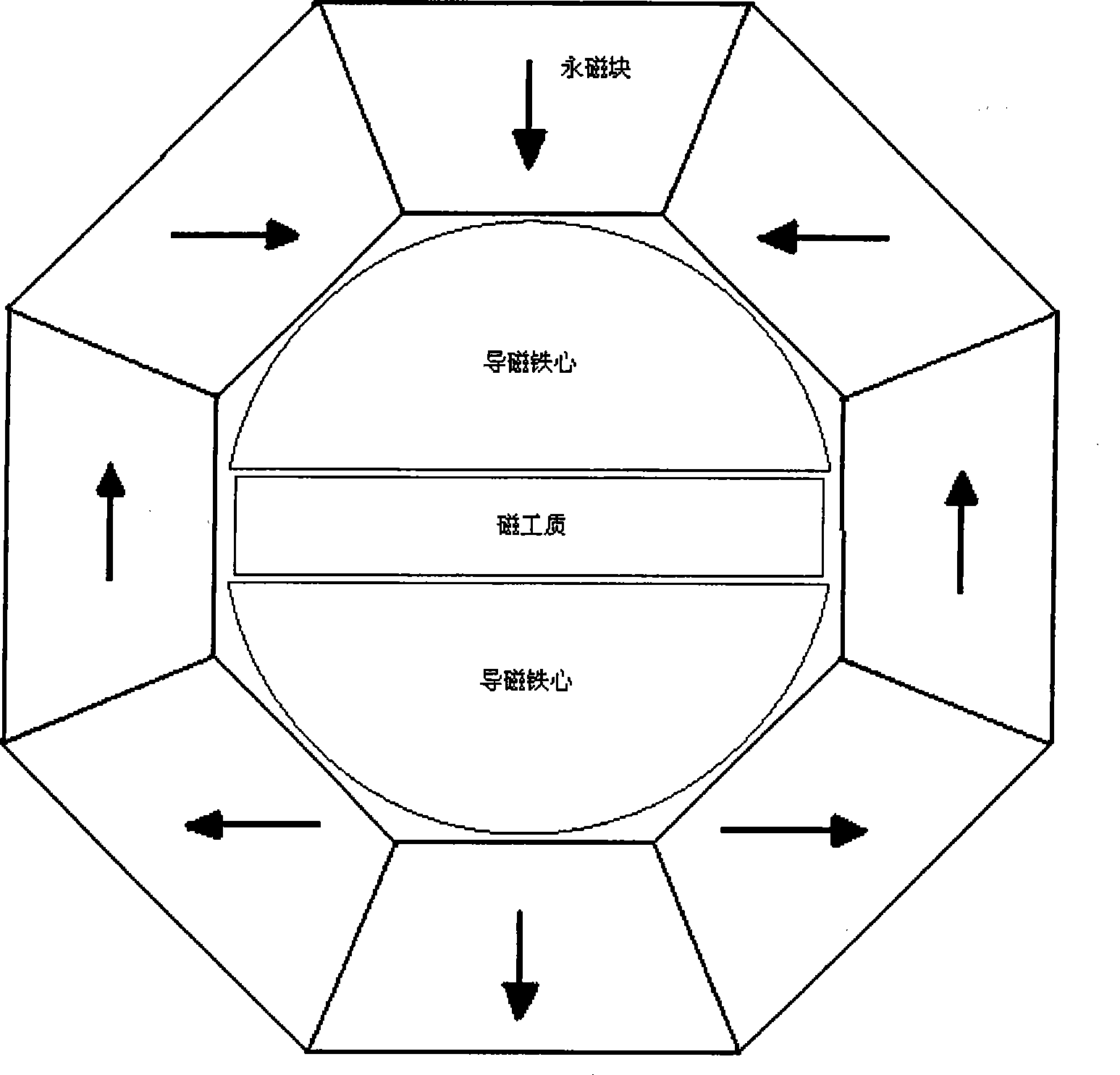
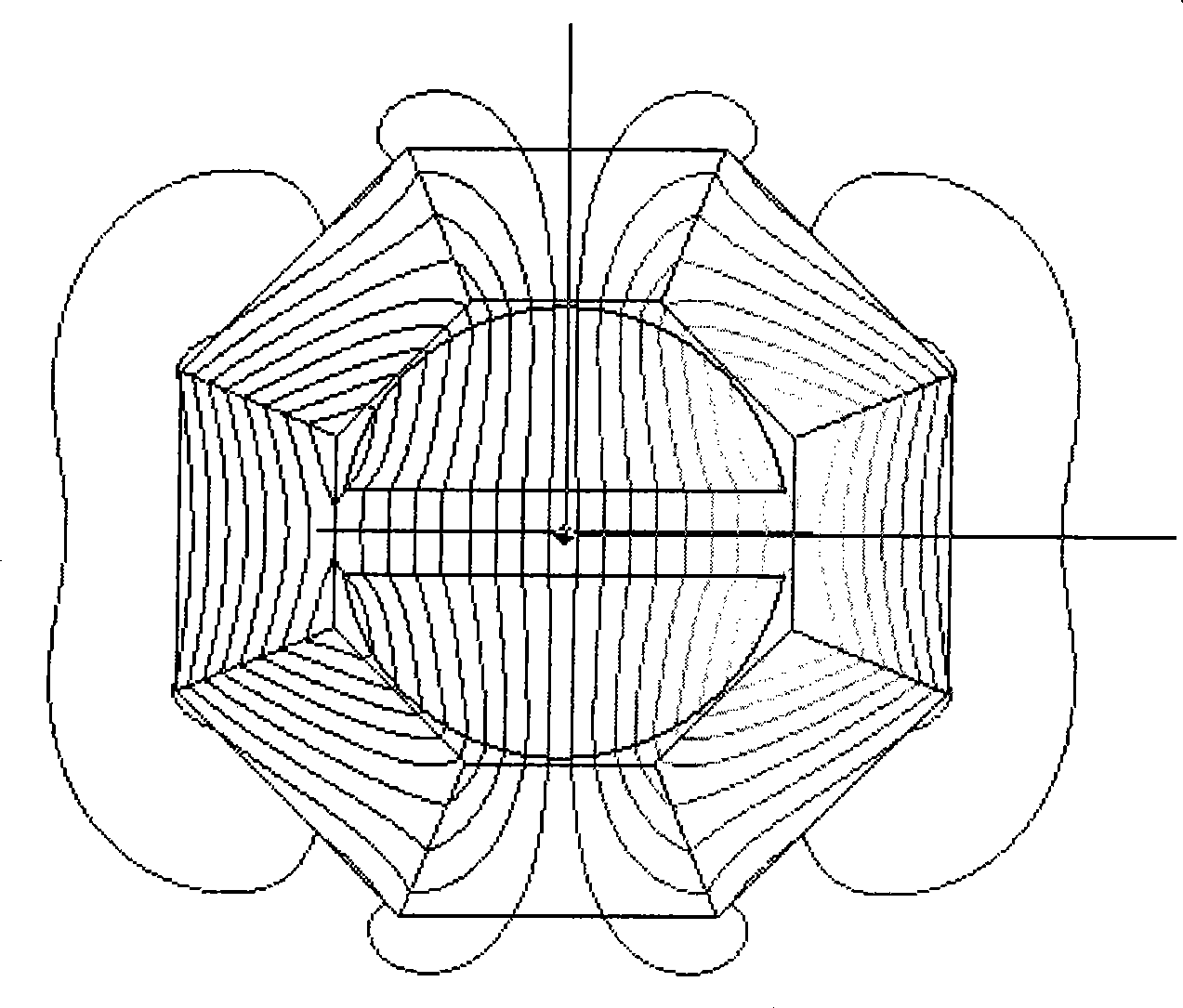
[0023] like figure 1 As shown, the Halbach hollow cylindrical permanent magnet of the stator is composed of 8 trapezoidal permanent magnets, and its magnetization direction is determined by the Halbach rotation theorem, as figure 1 indicated by the middle arrow. The permanent magnetic potential along the magnetization direction of the permanent magnet generates a bipolar magnetic field in the cavity of the hollow cylinder.

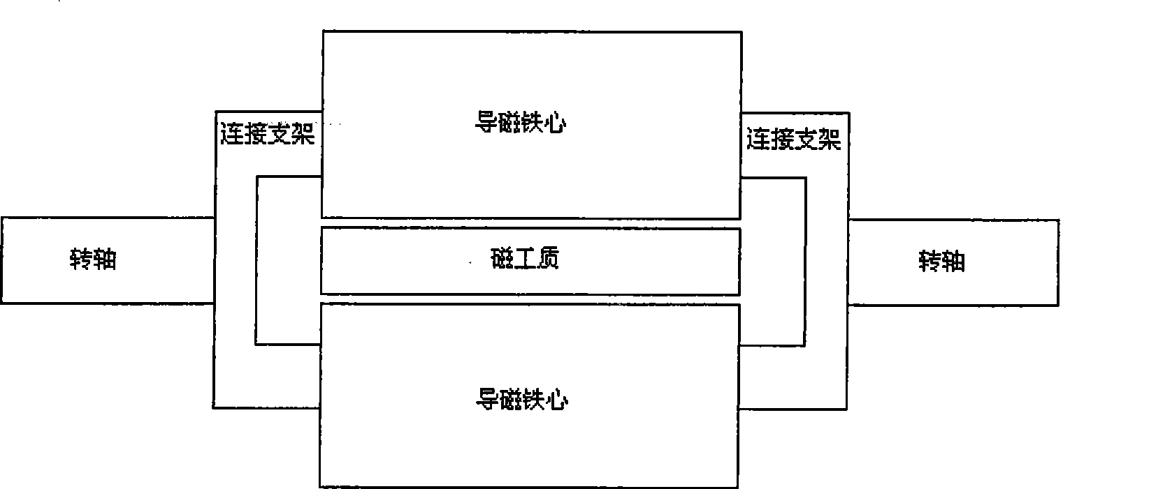
[0024] The shaft of the rotor is located at the rotation center of the rotor, and the centerlines of the two rotor shafts coincide with the geometric centerline of the stator. The two magnetic cores of the rotor are bow-shaped cylindrical bodies in cross-section, which are connected to the shaft through the connecting bracket to form a one-piece set on the shaft, such as figure 2 shown. The curved side of the bow-shape...


PUM


Abstract

The invention relates to a rotary magnetic refrigeration permanent magnet system. A stator is a hollow cylindrical permanent magnet based on the Halbach rotation principle. The hollow cylindrical magnet is formed by assembling permanent magnetic blocks with the central shaft on the cross section of the magnet. The magnetizing directions of the permanent magnetic blocks are determined by the Halbach rotation principle. A rotor mainly comprises magnetic conductive iron cores, a magnetic working substance and a rotating shaft. A rotator shaft is positioned in the central rotation position of therotor. The central lines of two sections of rotator shaft are overlapped with the geometric center line of the rotor. Two magnetic conductive iron cores of the rotor are cylindrical bodies with bow-shaped cross sections, connected with the rotating shaft as a whole through a connection bracket and sleeved on the rotating shaft. The magnetic working substance is tightly fixed between the two magnetic conductive iron cores and rotates along with the magnetic conductive iron cores. The magnetic working substance is a cuboid. A certain clearance is left between the stator and the rotor.

Description

technical field [0001] The present invention relates to a permanent magnet system, in particular to a permanent magnet system for rotating magnetic refrigeration equipment. Background technique [0002] Magnetic refrigeration is a green and environmentally friendly new refrigeration technology. Compared with traditional vapor compression refrigeration, magnetic refrigeration uses magnetic materials as the refrigerant, which has no damage to the ozone layer and no greenhouse effect. The newly developed magnetic refrigerator uses a water-based heat transfer fluid to minimize the global warming effect. [0003] Magnetic refrigeration technology is a refrigeration technology based on the principle of magnetocaloric effect. The magnetocaloric effect means that when the magnetic working medium (magnetic refrigeration material) is magnetized by the magnetic field, the magnetic order of the system is strengthened, and heat is released to the outside, and then demagnetized, the mag...

Claims


Application Information

Patent Timeline
Patent Type & Authority Patents(China)
IPC IPC(8): F25B21/00H01F7/02
CPCY02B30/66Y02B30/00
Inventor 夏东
Owner INST OF ELECTRICAL ENG CHINESE ACAD OF SCI
Why Eureka
Try Eureka