
A cylindrical primary permanent magnet transverse flux linear motor

A linear motor and transverse magnetic flux technology, applied in the direction of electromechanical devices, electrical components, electric components, etc., can solve problems such as difficult installation and assembly, asymmetric bilateral air gaps, complex structures, etc., and achieve convenient and easy assembly and small burden on guide rail bearings , The effect of high torque density

Active Publication Date: 2022-03-01
CHINA UNIV OF MINING & TECH
View PDF6 Cites 0 Cited by
  • Summary
  • Abstract
  • Description
  • Claims
  • Application Information

AI Technical Summary

Problems solved by technology

[0005] The linear motor obtained by expanding the traditional rotating motor is usually a unilateral structure. There is a normal force between the moving stator and the unilateral magnetic pull. The unilateral magnetic pull is usually large, which will cause greater friction between the mover and the stator. Force, increasing the burden on the moving stator bearing affects the performance and life of the motor, so there is usually a double-sided structure, which can theoretically reduce the normal magnetic pull, but due to the existence of technical problems, there will be asymmetry of the double-sided air gap. The situation of edge magnetic pull cannot be completely resolved
The cylindrical type is distributed with circular stators. Under the condition of reasonable design and standardized installation, it can effectively offset the radial magnetic pull. Both the winding part and the permanent magnet excitation part of the permanent magnet linear motor have the problems of complex structure and difficult installation and assembly, so there is still a lot of room for improvement in its structure

Method used


Image

  • A cylindrical primary permanent magnet transverse flux linear motor
  • A cylindrical primary permanent magnet transverse flux linear motor
  • A cylindrical primary permanent magnet transverse flux linear motor

Examples


Embodiment Construction

[0036] The technical solutions and beneficial effects of the present invention will be described in detail below in conjunction with the accompanying drawings.

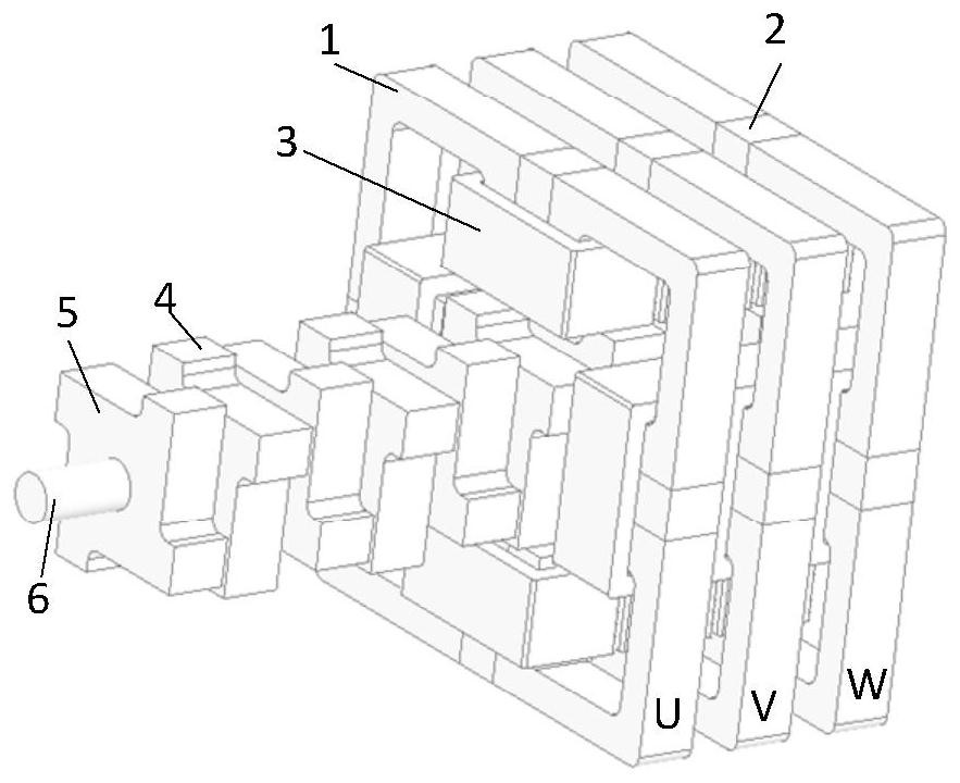
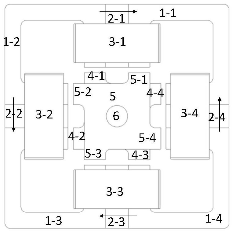
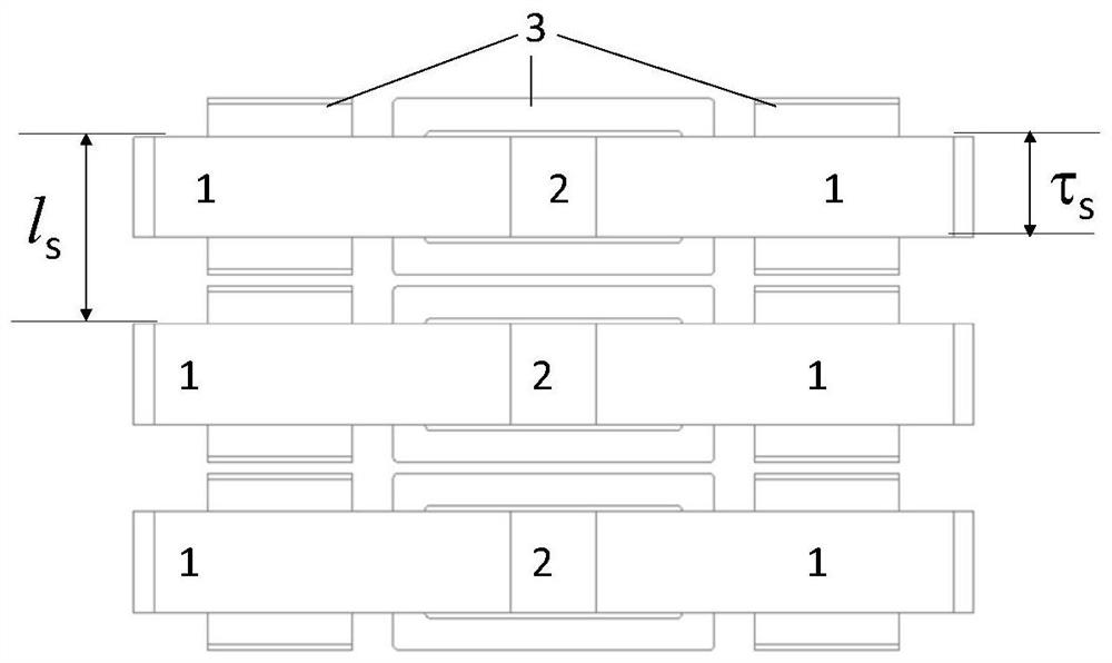
[0037] Figure 1(a) is a schematic structural diagram of a three-phase primary four-pole cylindrical primary permanent magnet transverse flux linear motor, including two parts, the primary and the secondary. The primary part includes several primary units with the same structure. Each primary unit is composed of primary magnetic components, armature windings and permanent magnets, and the secondary part is composed of secondary magnetic components and fixed shafts arranged in sequence; the primary and secondary magnetic components can be laminated by iron core silicon steel sheets It can also be molded from composite magnetically permeable materials. The secondary magnetically permeable parts adopt an asymmetric structure, and are sequentially staggered and fixed on the fixed shaft. Fig. 1 (b) is a kind of three-phase...


PUM


Abstract

The invention discloses a cylindrical primary permanent magnet type transverse flux linear motor, which includes a primary mechanism and a secondary mechanism. The primary mechanism includes several primary units with the same structure. N-sided or circular, the teeth of two adjacent primary magnetic conductive parts are connected by permanent magnets to form a magnetic pole on which the armature winding is wound; all primary units are arranged coaxially in sequence; the secondary mechanism includes a fixed The shaft and several secondary magnetically permeable parts, the secondary magnetically permeable parts include a yoke and N teeth, and the N teeth are evenly arranged on the outer periphery of the yoke, respectively aligned with the teeth at the same position in the N magnetic poles; Adjacent secondary magnetically permeable parts are staggered and arranged alternately. This kind of motor structure can realize the permanent magnet and winding on the primary side at the same time, and each phase is isolated and decoupled, the electromagnetics are independent of each other, the torque density is high, the design is flexible, the control is convenient, and the secondary side structure is simple and reliable.

Description

technical field [0001] The invention belongs to the technical field of motor design, in particular to a cylindrical primary permanent magnet transverse flux linear motor. Background technique [0002] When the linear motor drives the linear motion load, the conversion mechanism from the rotation to the linear motion of the rotary motor is omitted, so it has the advantages of simple overall structure, high position accuracy, fast response speed, and low noise. Improve the efficiency of the whole system. In recent years, with the application of linear drives more and more widely, linear motors have gradually become one of the hot spots of research and development, and have been widely used in military industry, aerospace, rail transportation, electromagnetic ejection and other fields. [0003] The motion direction of the transverse flux linear permanent magnet motor is perpendicular to the plane where the motor magnetic field path is located. The motor circuit and the motor m...

Claims


Application Information

Patent Timeline
Patent Type & Authority Patents(China)
IPC IPC(8): H02K41/03
CPCH02K41/031
Inventor 付东山伍小杰徐衍亮李小强夏晨阳于东升廖志娟
Owner CHINA UNIV OF MINING & TECH
Learn More