
Excitation control method for dual-axis excitation turbogenerator

A technology of turbo-generator and biaxial excitation, which is applied in the direction of synchronous generator control and generator control through magnetic field changes, which can solve the problem of the reduction of the ampere-turns of the excitation winding and the reduction of the synthetic excitation magnetomotive force, which limits the stable operation of the generator Limits, unfavorable power system stability and other issues, to achieve the effect of increasing the degree of freedom, realizing the same frequency and asynchronous operation, and reducing the system oscillation time

Pending Publication Date: 2019-04-05
NORTH CHINA ELECTRIC POWER UNIV (BAODING)
View PDF1 Cites 6 Cited by
  • Summary
  • Abstract
  • Description
  • Claims
  • Application Information

AI Technical Summary

Problems solved by technology

There is only one set of excitation winding on the rotor of a traditional synchronous generator, and the direction of its excitation magnetomotive force can only be fixed on the d-axis of the rotor, which limits the stable operation limit of the generator and is not conducive to the stability of the power system
In the dual-axis excitation generator with three sets of windings on the rotor, one set of windings is used as the damping winding, and the other two sets of windings are used as the exciting winding. Machine capacity reduction

Method used


Image

  • Excitation control method for dual-axis excitation turbogenerator
  • Excitation control method for dual-axis excitation turbogenerator
  • Excitation control method for dual-axis excitation turbogenerator

Examples


Embodiment

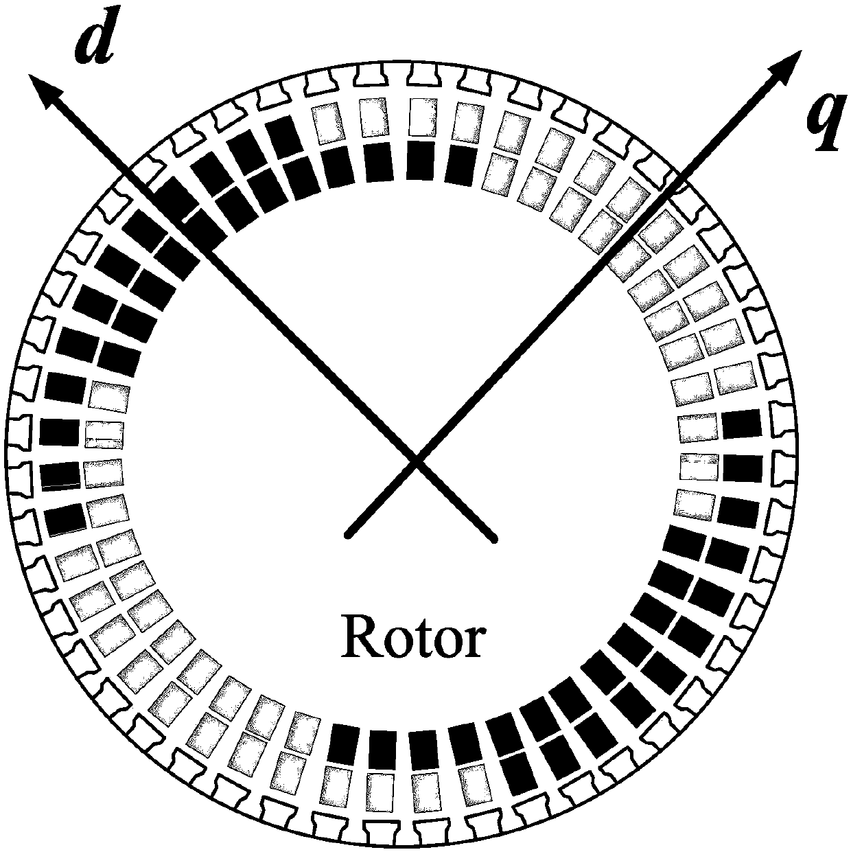
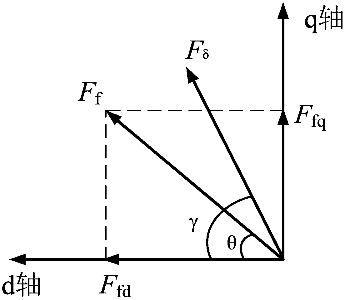
[0036] According to the technical scheme of the present invention, a 300MW biaxial excitation turbogenerator has been designed, the rotor cross section of this generator is as follows figure 1 As shown, the rotor is a two-pole hidden pole structure, and the two sets of windings on the rotor are perpendicular to each other in space; when the uniaxial excitation is applied, the d-axis excitation winding is fed with DC current, and the q-axis excitation winding is open; direct current respectively. A vector diagram of a magnetic field such as figure 2 shown.

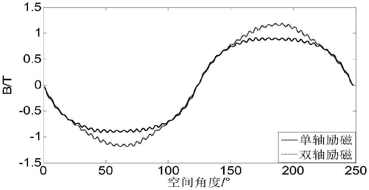
[0037] When the dual-shaft excitation turbogenerator has only one set of excitation windings to apply no-load excitation current, the air-gap flux density waveform and the air-gap flux density fundamental wave component when the iron core is saturated are ignored, such as image 3 As shown, the amplitude of the air-gap magnetic base wave is 0.8944T. When the two sets of excitation windings of the dual-shaft excitation t...


PUM


Abstract

The invention belongs to the technical field of the control of a two-axis excitation generator and particularly relates to an excitation control method for a two-axis excitation turbogenerator. The method comprises the steps that: two sets of excitation windings on d and q axes of a rotor are set, the excitation windings are uniformly distributed on the surface of the rotor and are symmetrical, winding axes are perpendicular to each other, direct current is introduced to the two sets of excitation windings to generate two excitation fundamental wave magnetomotive forces, the position of an airgap synthetic magnetomotive force relative to the rotor is changed by adjusting the proportions of the two excitation fundamental wave magnetomotive forces while a combined excitation magnetomotive force is maintained to be unchanged, and therefore, the static stability limit of the two-axis excitation turbine generator is improved. The two-axis excitation turbine generator can operate at any rotation speed under the corresponding excitation control, the same-frequency asynchronous operation of the generator is realized, the anti-interference ability of the generator is effectively improved,and the power supply reliability of a key area is ensured.

Description

technical field [0001] The invention belongs to the technical field of biaxial excitation generator control, and in particular relates to an excitation control method of a biaxial excitation turbogenerator. Background technique [0002] With the development of large-scale combined power systems, the structure and operation mode of the power grid are becoming more and more complex and changeable, especially for long-distance high-power transmission lines, "strong direct and weak AC" power grid structure, and new energy grid-connected operation modes. The stable operation of the power system brings huge security risks, and the reliability of the power system faces great challenges. Therefore, how to provide power system stability and reliability becomes very important. [0003] As an important component of the power system, the synchronous generator's stable operation ability has an important impact on the stability of the power system. There is only one set of excitation win...

Claims


Application Information

Patent Timeline
IPC IPC(8): H02P9/14H02P103/20
CPCH02P9/14H02P2103/20
Inventor 许国瑞罗超龙李伟力刘晓芳罗应立
Owner NORTH CHINA ELECTRIC POWER UNIV (BAODING)
Learn More