
Spatial mapping power fiber backbone communication network service path planning method and system

A service path and space mapping technology, applied in optical fiber transmission, transmission system, digital transmission system, etc., can solve the problem of unbalanced use of path resources and achieve the effect of improving the balance of resource use

Active Publication Date: 2019-04-05
STATE GRID CORP OF CHINA +1
View PDF7 Cites 0 Cited by
  • Summary
  • Abstract
  • Description
  • Claims
  • Application Information

AI Technical Summary

Problems solved by technology

[0004] Aiming at the technical limitations of the unbalanced use of business path resources in the existing power fiber optic backbone communication network, the purpose of the present invention is to provide a spatially mapped power fiber optic backbone communication network business path planning method and system, which can realize spatially mapped power Business path planning of optical fiber backbone communication network, effectively improving resource utilization balance of power optical fiber backbone communication network

Method used


Image

  • Spatial mapping power fiber backbone communication network service path planning method and system
  • Spatial mapping power fiber backbone communication network service path planning method and system
  • Spatial mapping power fiber backbone communication network service path planning method and system

Examples


Embodiment

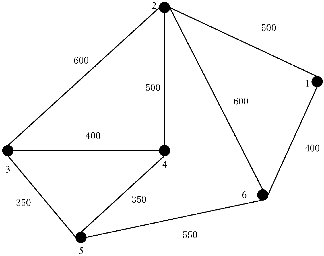
[0031] Example: such as figure 2 As shown, the power optical fiber backbone communication network contains N=6 nodes, and the routing path composed of multiple links between the paired nodes constitutes the service path carrying the electric power service, and the service realizes the transmission of service information through the links in the path.

[0032] In this embodiment, the number of network nodes in the power fiber optic backbone communication network is N=6, and the link fiber length information E between each pair of nodes i and node g ig (unit: kilometer) As shown in Table 1, positive infinity means no link connection; link wavelength capacity C(i, g) and link carrying current between each pair of node i and node g in the power optical fiber backbone communication network Table 2 shows the number of wavelengths f(i, g) occupied by service links after some services.

[0033] Table 1 Information table of optical fiber length of link between nodes

[0034] ...


PUM


Abstract

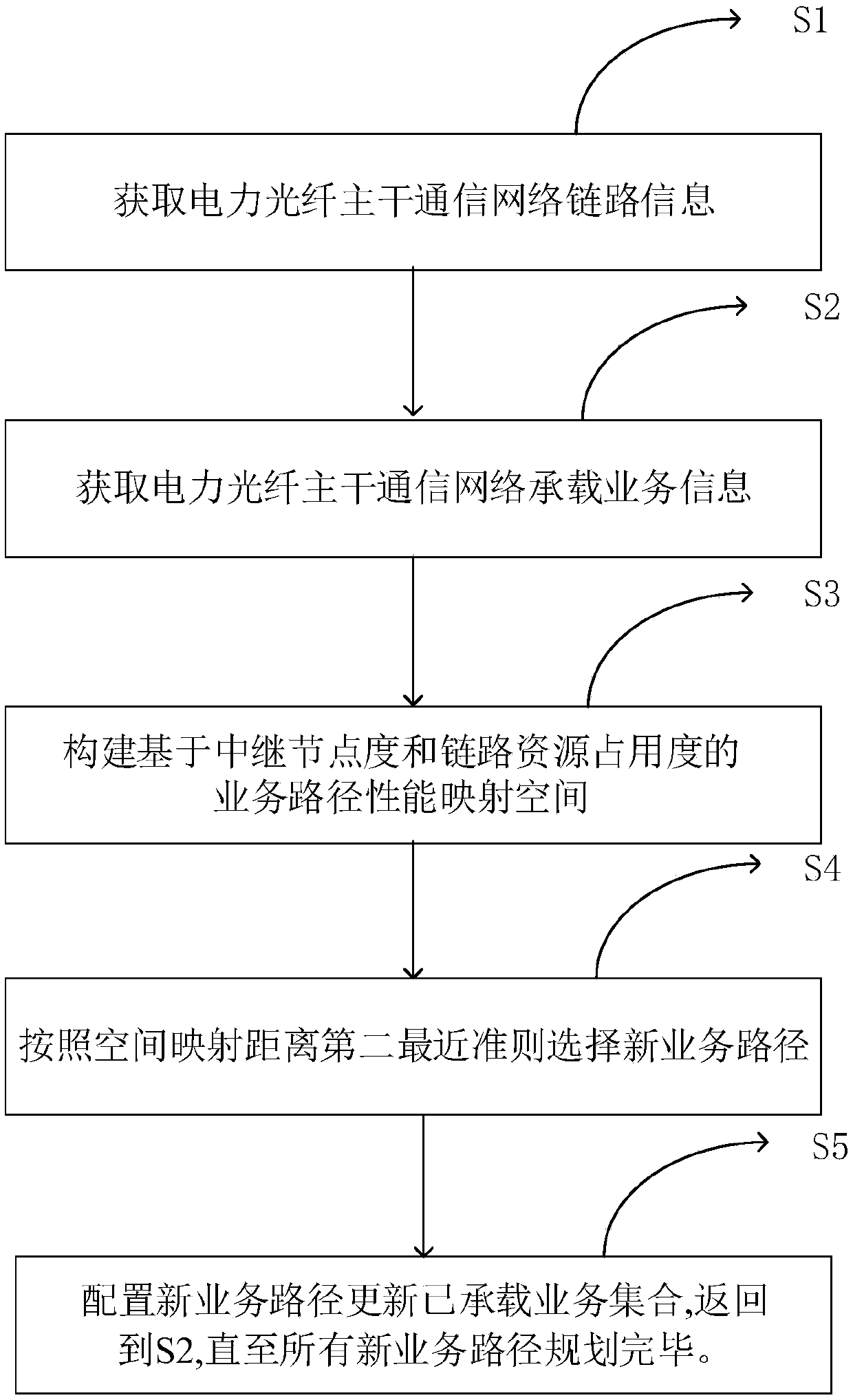
The invention relates to a spatial mapping power fiber backbone communication network service path planning method and system. The method comprises the steps of: acquiring power fiber backbone communication network link information; acquiring power fiber backbone communication network bearer service information; constructing a service path performance mapping space based on the relay node degree and the link resource occupation degree; selecting a new service path according to the second closest criterion of the spatial mapping distance; and configuring the new service path to update a bearerservice set until all the new service paths are completely planned. The spatial mapping power fiber backbone communication network service path planning method and system achieve the spatial mapping power fiber backbone communication network service path planning so as to effectively improve the usage balance of the power fiber backbone communication network resource.

Description

technical field [0001] The invention relates to the technical field of power fiber optic backbone communication, in particular to a method and system for planning a service path of a power fiber backbone communication network with spatial mapping. Background technique [0002] With the continuous construction of the smart grid and the rise of the energy Internet, the scale of the power optical fiber backbone communication network continues to expand, the grid structure becomes more and more complex, the structure becomes more and more complex, the business types become more diverse, and the transmission quality requirements become increasingly precise. The role has changed to a new type of power exchange system node integrating power collection, power transmission, power storage, power distribution and user interaction, which brings new challenges to the planning of power fiber optic communication networks. [0003] The business path planning of the power optical fiber backb...

Claims


Application Information

Patent Timeline
Patent Type & Authority Applications(China)
IPC IPC(8): H04B10/25H04L12/24
CPCH04B10/25H04L41/145
Inventor 李疆生金广祥李军王浩张霄张文英刘金梅刘敏陆俊林伟伟
Owner STATE GRID CORP OF CHINA
Learn More