
3D printing method and system for customizing appearance of three-dimensional model

A three-dimensional model, 3D printing technology, applied in the field of 3D printing, can solve the problem that the tool can not meet the requirements of the appearance of the 3D printing model

Active Publication Date: 2019-04-09
YANTAI JIERUI NETWORK TRADING
View PDF5 Cites 7 Cited by
  • Summary
  • Abstract
  • Description
  • Claims
  • Application Information

AI Technical Summary

Problems solved by technology

[0006] In view of the above reasons, some simple and easy-to-use 3D printing-oriented model customization tools have appeared, but they can only choose from several pre-set styles for existing models, which still cannot allow users, especially the appearance Users in industries such as design and children's creative education can fully customize the appearance according to their own needs, so the current tools are far from meeting the requirements of users to customize the appearance of 3D printing models

Method used


Image

  • 3D printing method and system for customizing appearance of three-dimensional model
  • 3D printing method and system for customizing appearance of three-dimensional model

Examples


Embodiment 1

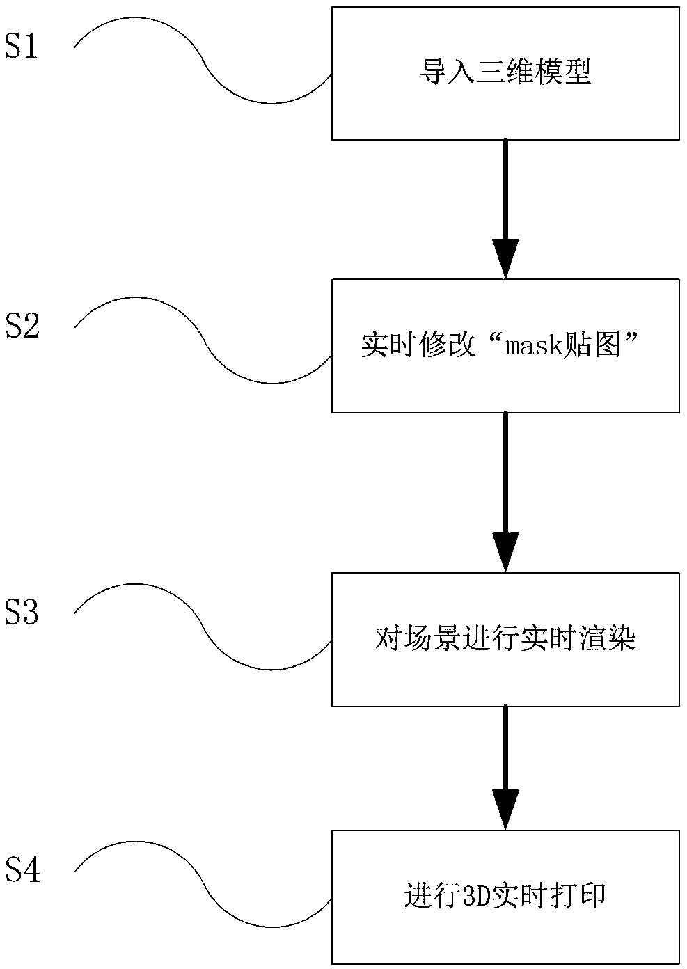
[0047] Please refer to figure 1 As shown, the flow chart of the 3D printing method for customizing the appearance of a three-dimensional model, a 3D printing method for customizing the appearance of a three-dimensional model, the steps are as follows:

[0048] S1: Import the 3D model; import the white mold of the Snoopy model modeled by 3Dmax into the 3D engine;

[0049] S2: Modify the "mask texture" in real time; write a script to obtain the brush shape, size, real-time collision position between the brush and the model, and the trajectory of the brush, according to the material, size, and coordinates of the collision position between the brush and the model , The trajectory of the brush draws the "mask map" in real time.

[0050] S3: Render the scene in real time, and generate the appearance of the model in the process of drawing with different brushes.

[0051] Step 3.1: Write or call a shader to achieve the mixing effect of different textures in different channels of the "...

Embodiment 2

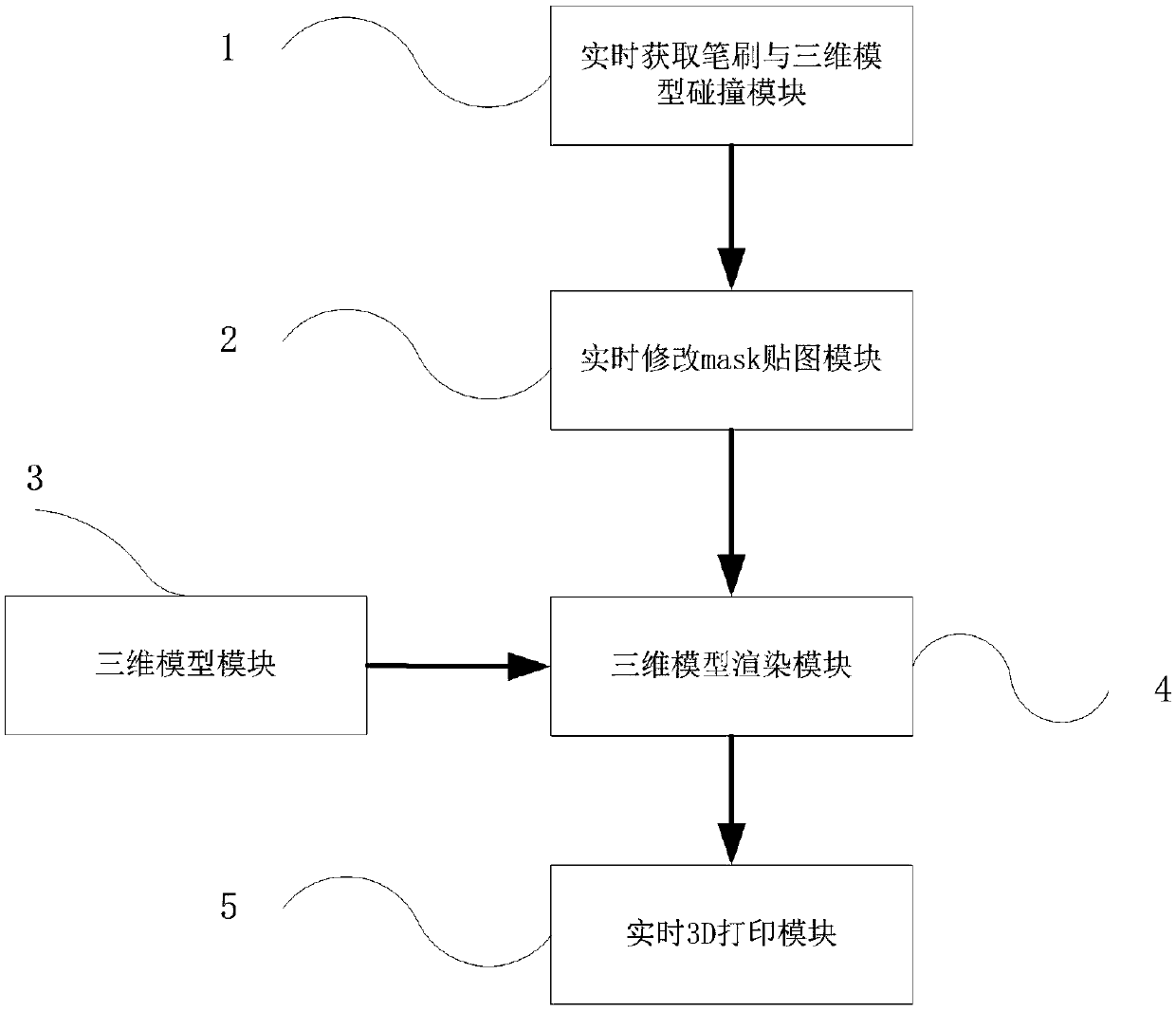
[0062] Please refer to figure 2 As shown, a 3D printing system for customizing the appearance of a 3D model includes a real-time acquisition brush and 3D model collision module 1, a real-time modification "mask texture" module 2, a 3D model module 3, a 3D model rendering module 4 and a real-time 3D printing module 5;

[0063] The real-time acquisition brush and three-dimensional model collision module 1 is used to obtain the real-time data processing of the collision position between the brush and the three-dimensional model used by the user in the three-dimensional virtual space. The real-time data includes the coordinate points of the collision between the brush and the three-dimensional model, and the The point is converted into the UV coordinates of the "mask texture". The UV coordinates of the "mask texture" mentioned here refer to the coordinates of the "mask texture" in the two-dimensional plane where it is located. The two-dimensional plane where the "mask texture" i...


PUM


Abstract

The invention discloses a 3D printing method for customizing the appearance of a three-dimensional model. The method includes the following steps that S1, the three-dimensional model is imported; S2,a mask chartlet is modified in real time; S3, a scene is rendered in real time; and S4, 3D real-time printing is carried out. S3 includes the procedures that S3.1, a tinter is compiled or called; S3.2, the tinter attribute of the three-dimensional model in S1 is modified into the tinter in S3.1, and the mask chartlet attribute of the tinter in S3.1 is modified into the mask chartlet modified in S2; S3.3, all channels are mixed in real time through the tinter in S3.1 according to the mask chartlet in S2, and the effect of describing different patterns for the model in real time is achieved; andS3.4, the dynamic customized appearance of the three-dimensional model in S1 is generated. Thus, the appearance of the three-dimensional model is individually customized easily and quickly. The invention further discloses a 3D printing system for the customizing the appearance of the three-dimensional model.

Description

technical field [0001] The invention relates to the field of 3D printing, in particular to a 3D printing method and system for customizing the appearance of a three-dimensional model. Background technique [0002] Rapid prototyping technology is a technology based on a three-dimensional model established by a computer, which uses various adhesive materials to construct a three-dimensional model by layer-by-layer superposition. This technology has been widely used in developed countries. [0003] 3D printing is a new technology in the field of rapid prototyping. Its working principle is similar to inkjet printing, that is, it responds to the digital signal of the computer, so that the molten material or binder in the working cavity of the nozzle forms liquid droplets in an instant, and the liquid droplets are formed at a certain rate. The speed is extruded from the nozzle and sprayed onto the support model to form the shape of the outline. After the thin layer is solidified, ...

Claims


Application Information

Patent Timeline
Patent Type & Authority Applications(China)
IPC IPC(8): B29C64/386B29C64/393B29C64/112B29C64/20B33Y50/00B33Y50/02B33Y30/00B33Y10/00
CPCB33Y10/00B33Y30/00B33Y50/00B33Y50/02B29C64/112B29C64/20B29C64/386B29C64/393
Inventor 王涛牟文青李腾安士才杨斌贺业凤吴忠洋刘鹏赵影
Owner YANTAI JIERUI NETWORK TRADING
Learn More