Efficient cable winding drum with automatic cable arranging function

An automatic rowing and functional technology, applied in the direction of conveying filamentous materials, thin material processing, transportation and packaging, etc., can solve the problems of low winding efficiency of cable reels and uneven distribution of cables, and achieve reasonable utilization of reels Tube space, improve the distribution range of cables, and facilitate transportation and storage

Inactive Publication Date: 2019-04-09
新乡市恒德机电有限公司
View PDF6 Cites 9 Cited by
  • Summary
  • Abstract
  • Description
  • Claims
  • Application Information

AI Technical Summary

Problems solved by technology

[0003] The purpose of the present invention is to provide a high-efficiency cable reel with automatic cable discharge function in order to solve the technical problems of low winding efficiency and uneven distribution of cables in existing cable reels

Method used


Image

  • Efficient cable winding drum with automatic cable arranging function
  • Efficient cable winding drum with automatic cable arranging function
  • Efficient cable winding drum with automatic cable arranging function

Examples


Embodiment 1

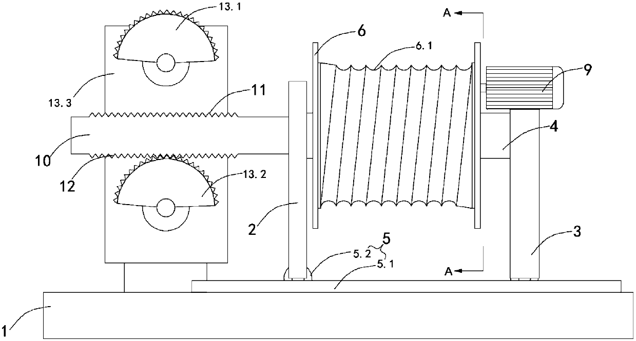
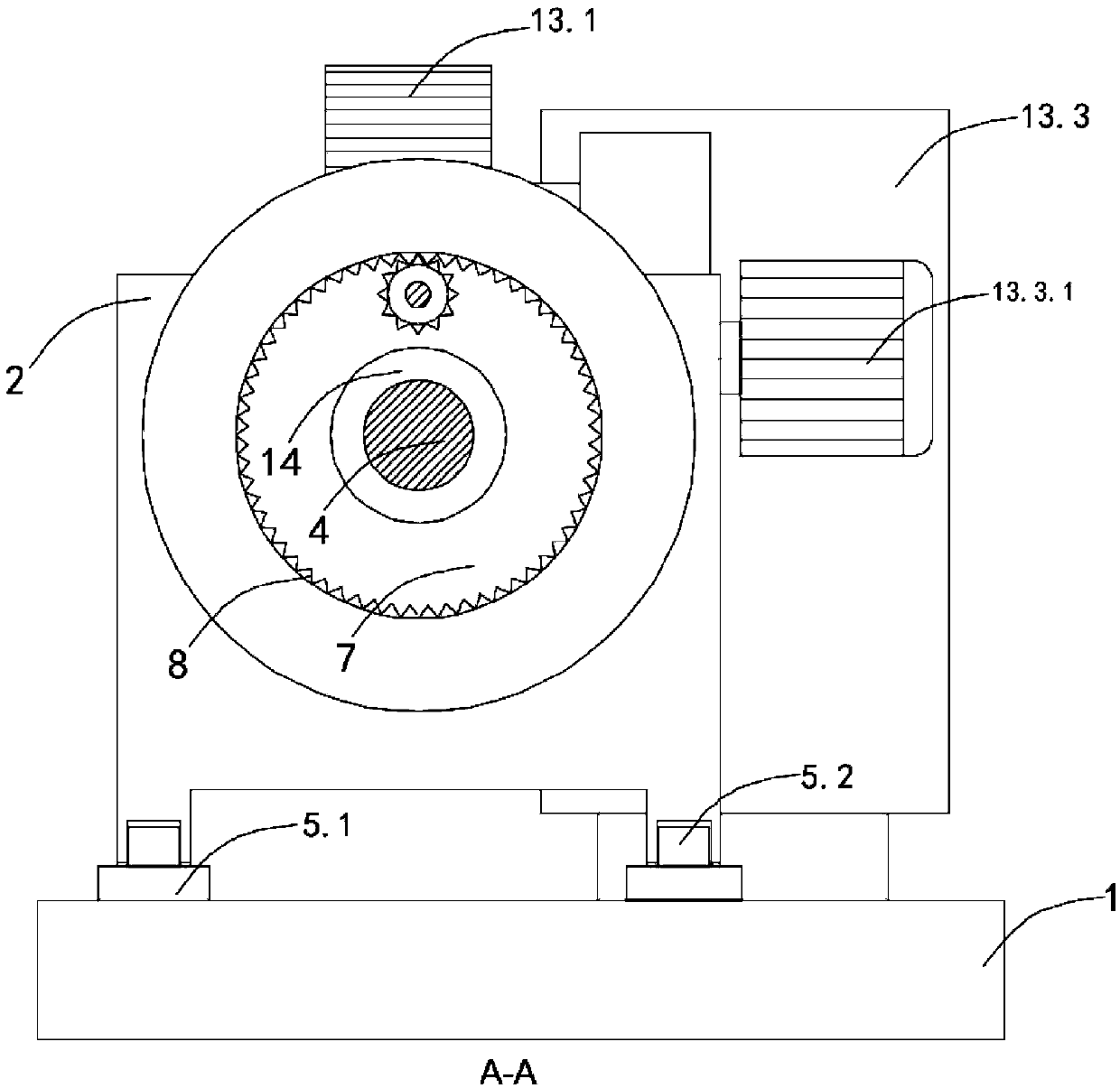
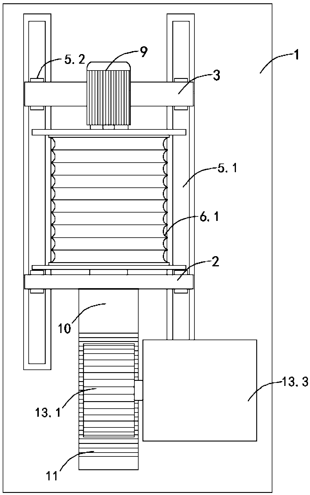
[0028] like Figure 1 to Figure 4 As shown, this embodiment provides a high-efficiency cable reel 6 with automatic cable removal function, including a base 1, a roller mechanism is provided on the right side of the top surface of the base 1, and the roller mechanism includes a left fixing plate 2 and a right fixing plate 3 and the connecting shaft 4 fixed between the left fixed plate 2 and the right fixed plate 3, the bottom of the left fixed plate 2 and the right fixed plate 3 are provided with a sliding mechanism 5 fixed on the top surface of the base 1, and the connecting shaft 4 passes through multiple The first bearing is provided with a reel 6, and the right wall of the reel 6 is provided with a ring groove 7 around the axis of the reel 6, and the inner wall of the ring groove 7 is provided with a first tooth groove 8, and the first tooth groove 8 is connected with the gear arranged inside the ring groove 7. Cooperate, the gear is connected with the rotating motor 9 fixe...

Embodiment 2

[0031] like Figure 1 to Figure 3 As shown, this embodiment is further optimized on the basis of embodiment 1, specifically:

[0032]The sliding mechanism 5 includes two slide rails 5.1 fixed on the top surface of the base 1 and parallel to each other. The direction of the slide rails 5.1 is the same as that of the connecting shaft 4 axis. The roller 5.2 of right fixed plate 3.

[0033] In this embodiment, there is rolling friction between the slide rail 5.1 and the roller 5.2, so that the resistance of the left and right reciprocating motion of the entire cable reel 6 is minimized, and the purpose of reducing energy consumption and cost is achieved.

Embodiment 3

[0035] like Figure 1 to Figure 3 As shown, this embodiment is further optimized on the basis of embodiment 1, specifically:

[0036] The transmission device 13 includes a first incomplete gear 13.1 that can mesh with the second tooth groove 11, a second incomplete gear 13.2 that can mesh with the third tooth groove 12 and has the same structure as the first incomplete gear 13.1, and is fixed on the base In the power case 13.3 on 1, the range of tooth groove angles of the first incomplete gear 13.1 and the second incomplete gear 13.2 is between 170° and 180°, and the number of tooth grooves of the first incomplete gear 13.1 is the same as that of the second tooth The number of tooth grooves of the groove 11 is equal, and the second incomplete gear 13.2 is not meshed with the third tooth groove 12 when the first incomplete gear 13.1 meshes with the second tooth groove 11, and the turning direction of the first incomplete gear 13.1 is the same as that of the second incomplete ge...


PUM


Abstract

The invention discloses an efficient cable winding drum with an automatic cable arranging function, relates to the technical field of cable winding drum equipment, and aims to solve the technical problems that the winding efficiency of an existing cable winding drum is low and the distribution of cables is not uniform. The efficient cable winding drum comprises a base, a roller mechanism is arranged on the right side of the top surface of the base, the roller mechanism comprises a left fixing plate, a right fixing plate and a connecting shaft, a sliding mechanism is arranged at the bottom of the left fixing plate and the bottom of the right fixing plate, a winding drum body is arranged on the connecting shaft, an annular groove is formed in the right wall of the winding drum body around the axis of the winding drum body, first tooth grooves are formed in the inner wall of the annular groove, the first tooth grooves are matched with a gear arranged inside the annular groove, the gear isconnected with a rotating motor, a toothed plate is perpendicularly fixed on the left wall of the left fixing plate, the top surface of the toothed plate is parallel to the top surface of the base and is provided with second tooth grooves, the bottom surface of the toothed plate is parallel to the top surface of the base and is provided with third tooth grooves which are the same as the second tooth grooves in structure, and the second tooth grooves and the third tooth grooves are meshed with a transmission device. The efficient cable winding drum with the automatic cable arranging function has the advantages of being high in wiring efficiency, uniform in winding distribution and high in reliability.

Description

technical field [0001] The invention relates to the technical field of cable reel equipment, and more specifically relates to a high-efficiency cable reel with automatic cable discharge function. Background technique [0002] In today's heavy industry, a cable reel is a piece of heavy machinery that can be used for electric winches on aircraft. The existing cable drums used for electric winches, in order to improve the efficiency of automation work, mainly use the motor to drive the drum to wind the cables, but the structure is complex and inconvenient to use. Do not use too high a winding speed, otherwise it will significantly increase the unevenness of the cables on the core of the cable reel, which will cause the cables on the core of the reel to overlap to form protrusions and depressions, making the The cable drum cannot continue to wind normally, resulting in low winding efficiency, and it is inconvenient to adjust the height of the wound coils into bundles, resulting...

Claims


Application Information

Patent Timeline
Patent Type & Authority Applications(China)
IPC IPC(8): B65H54/28
CPCB65H54/2803B65H2701/34
Inventor 李超周卫崔秀芹
Owner 新乡市恒德机电有限公司
Why Eureka
Try Eureka