Textile fabric winder

A technology for textile fabrics and winders, which is applied in the direction of winding strips, thin material handling, transportation and packaging, etc., can solve the problems of slow winding speed, loose fabrics, time-consuming and labor-intensive, etc., to reduce the number of winding turns, The effect of speeding up the winding speed and improving the winding quality

Active Publication Date: 2019-04-09
平顶山市碧盈家纺有限公司
View PDF14 Cites 2 Cited by
  • Summary
  • Abstract
  • Description
  • Claims
  • Application Information

AI Technical Summary

Problems solved by technology

The cloth is usually rolled by covering it on the drum, and the staff rotates the drum for winding. This first requires the staff to manually wind the cloth on the drum several times to fix one end of the textile cloth. When the production scale is large, the output quantity is large. , and this is not only time-consuming and labor-intensive, but also very troublesome; limited by the size of the drum, the diameter of the fabric winding is fixed, which will inevitably require more winding times, and the winding speed is very slow; the quality requirements of the current market for fabrics are only increasing. However, such a winding method makes the fabric looser, and wrinkles often appear on the surface, which not only affects the aesthetics of the fabric, but also greatly reduces the overall quality of the fabric, which cannot meet the needs of the market.

Method used


Image

  • Textile fabric winder
  • Textile fabric winder
  • Textile fabric winder

Examples


Embodiment 1

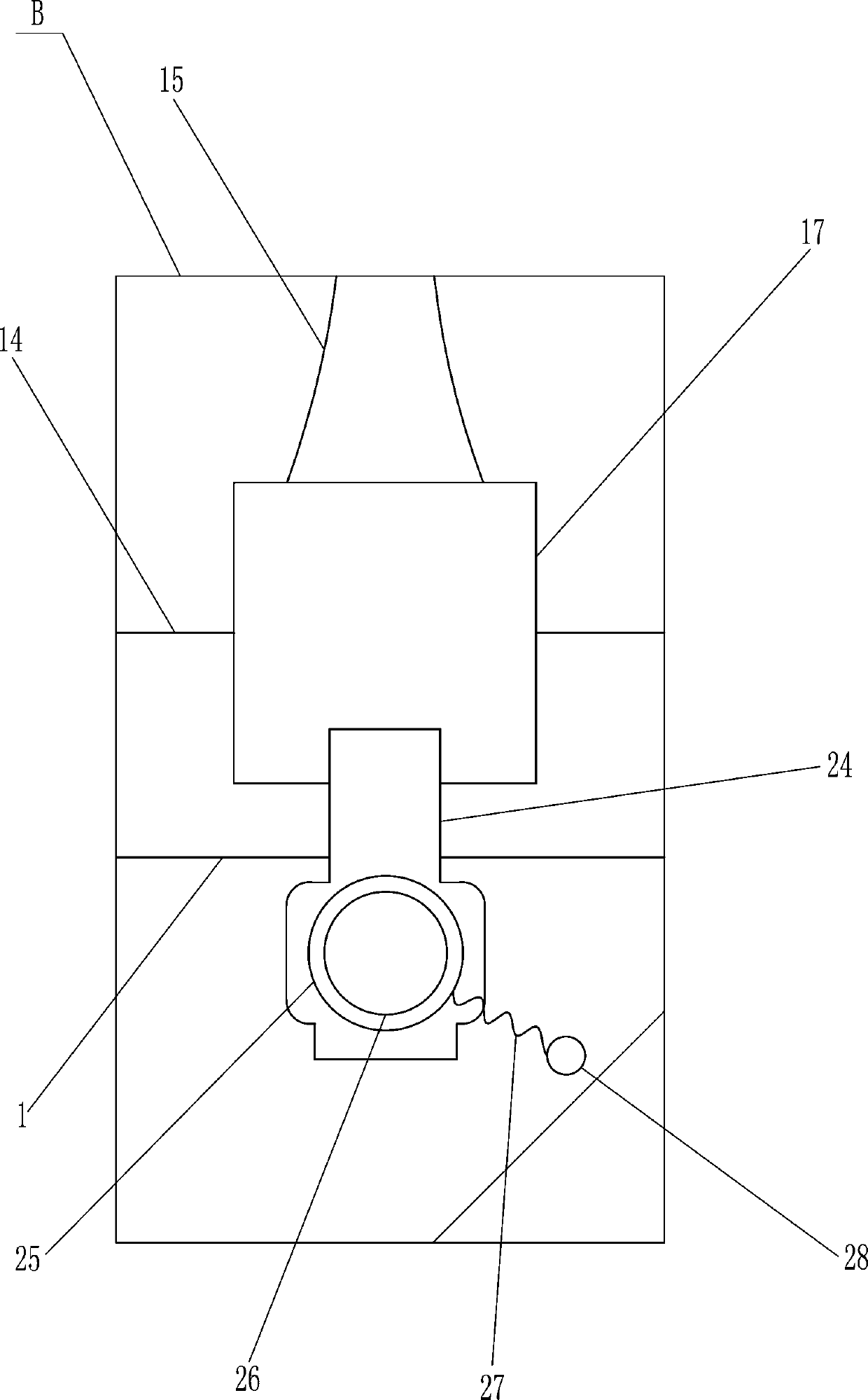
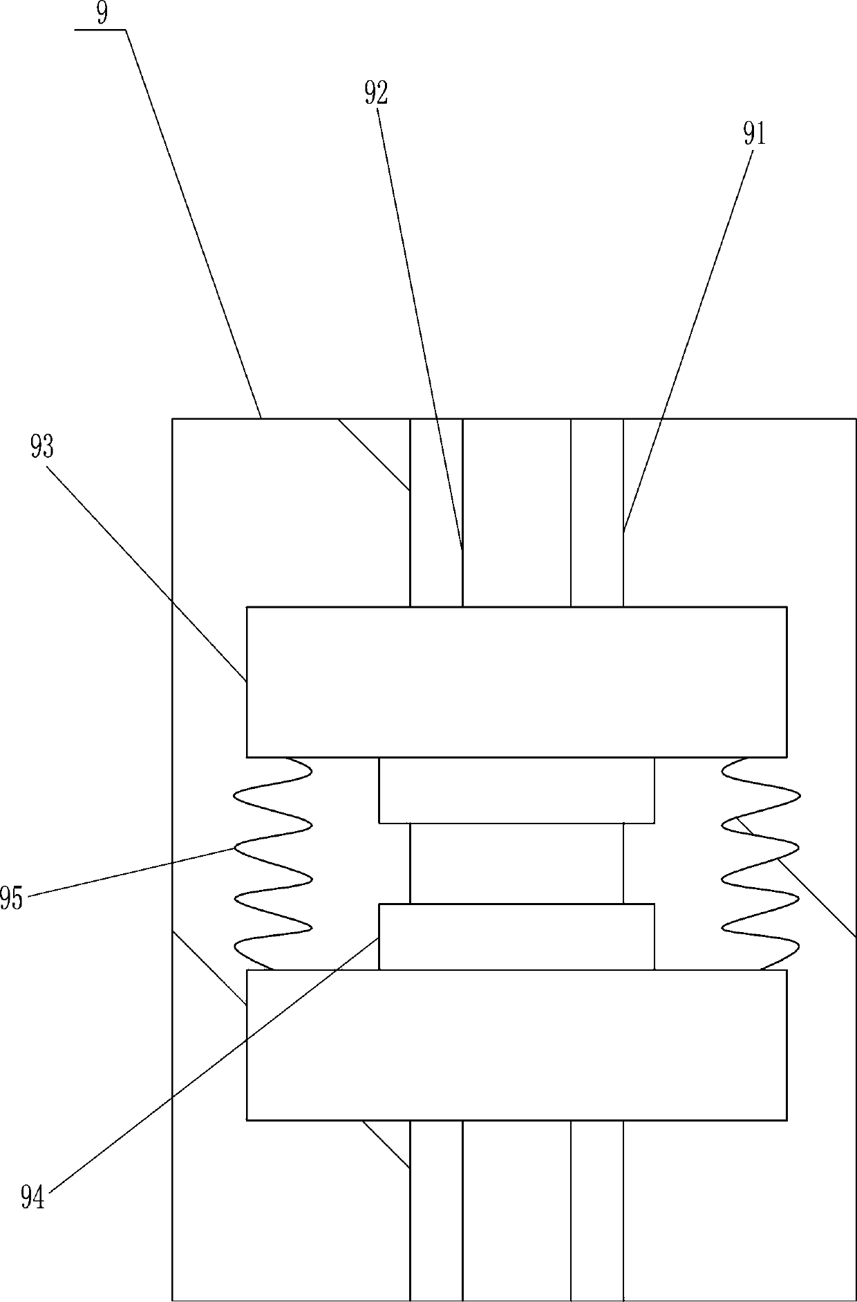
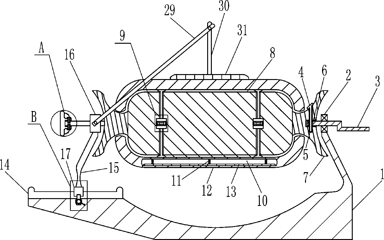
[0022] A textile cloth winder such as Figure 1-4 As shown, it includes base 1, bearing seat 2, rotating rod 3, first bolt 4, connecting column 7, rotating column 8, adjusting device 9, second spring 11, lifting plate 12, first pressing block 13, straight slide Rail 14, pole 15, fixed cover 16, slide block 17 and fixed rod 18, bearing seat 2 is installed on the right side of base 1 top, and rotating rod 3 is connected with interference in bearing seat 2, and rotating rod 3 left part has the second A threaded hole 6, the right part of the connecting column 7 has a cross hole 5, the left part of the rotating rod 3 is located in the cross hole 5, the first threaded hole 6 is internally screwed with the first bolt 4, and the first bolt 4 is passed through the cross hole 5 , the middle part of the connecting column 7 is connected with a rotating column 8, and the left and right parts of the front side of the rotating column 8 are provided with an adjusting device 9, and the parts o...

Embodiment 2

[0024] A textile cloth winder such as Figure 1-4 As shown, it includes base 1, bearing seat 2, rotating rod 3, first bolt 4, connecting column 7, rotating column 8, adjusting device 9, second spring 11, lifting plate 12, first pressing block 13, straight slide Rail 14, pole 15, fixed cover 16, slide block 17 and fixed rod 18, bearing seat 2 is installed on the right side of base 1 top, and rotating rod 3 is connected with interference in bearing seat 2, and rotating rod 3 left part has the second A threaded hole 6, the right part of the connecting column 7 has a cross hole 5, the left part of the rotating rod 3 is located in the cross hole 5, the first threaded hole 6 is internally screwed with the first bolt 4, and the first bolt 4 is passed through the cross hole 5 , the middle part of the connecting column 7 is connected with a rotating column 8, and the left and right parts of the front side of the rotating column 8 are provided with an adjusting device 9, and the parts o...

Embodiment 3

[0027] A textile cloth winder such as Figure 1-4As shown, it includes base 1, bearing seat 2, rotating rod 3, first bolt 4, connecting column 7, rotating column 8, adjusting device 9, second spring 11, lifting plate 12, first pressing block 13, straight slide Rail 14, pole 15, fixed cover 16, slide block 17 and fixed rod 18, bearing seat 2 is installed on the right side of base 1 top, and rotating rod 3 is connected with interference in bearing seat 2, and rotating rod 3 left part has the second A threaded hole 6, the right part of the connecting column 7 has a cross hole 5, the left part of the rotating rod 3 is located in the cross hole 5, the first threaded hole 6 is internally screwed with the first bolt 4, and the first bolt 4 is passed through the cross hole 5 , the middle part of the connecting column 7 is connected with a rotating column 8, and the left and right parts of the front side of the rotating column 8 are provided with an adjusting device 9, and the parts of...


PUM


Abstract

The invention relates to a winder, in particular to a textile fabric winder. The invention aims to solve the technical problem so as to provide the textile fabric winder convenient to fix cloth and capable of adjusting the winding diameter size and soothing and compacting the cloth. The textile fabric winder comprises a base, a bearing seat, a rotary rod, a first bolt, a connecting pillar, a rotating column, an adjusting device, a second spring, lifting plates, a first pressing block, a straight sliding rail, a support rod and the like, wherein the bearing seat is arranged on the right side ofthe top part of the base; the rotary rod is in interference connection into the bearing seat; a first threaded hole is formed in the left part of the rotary rod; a cross-shaped hole is formed in theright part of the connecting pillar; the left part of the rotary rod is located in the cross-shaped hole; and the first bolt is screwed in the first threaded hole. According to the textile fabric winder provided by the invention, working personnel presses one end of the cloth through the first pressing block, so that the cloth can be conveniently and quickly fixed; and through screwing a nut, thelifting plates on the upper part and the lower part are opened toward the outer side, and the cloth winding diameter size can be adjusted according to the needs, so that the winding turn number can bereduced, and the winding speed is accelerated.

Description

technical field [0001] The invention relates to a winder, in particular to a textile cloth winder. Background technique [0002] Textile fabrics are all formed through raw materials, spinning, weaving, dyeing and finishing. These processes are indispensable. After the fabrics are processed, they need to be rolled and packaged to make finished products for the market. The cloth is usually rolled by covering it on the drum, and the staff rotates the drum for winding. This first requires the staff to manually wind the cloth on the drum several times to fix one end of the textile cloth. When the production scale is large, the output quantity is large. , and this is not only time-consuming and labor-intensive, but also very troublesome; limited by the size of the drum, the diameter of the fabric winding is fixed, which will inevitably require more winding times, and the winding speed is very slow; the quality requirements of the current market for fabrics are only increasing. Ho...

Claims


Application Information

Patent Timeline
Patent Type & Authority Applications(China)
IPC IPC(8): B65H75/22B65H75/24B65H75/28B65H19/30B65H23/34
CPCB65H19/30B65H23/34B65H75/22B65H75/241B65H75/285B65H2701/1133
Inventor 丁予泽
Owner 平顶山市碧盈家纺有限公司
Why Eureka
Try Eureka