Crane for water conservancy project construction

A technology of water conservancy projects and cranes, which is applied in the direction of cranes, etc., can solve the problems of time-consuming and labor-intensive leveling of the site, and achieve the effects of saving time and effort for support, preventing rollover, and shortening the preparation work in the early stage

Inactive Publication Date: 2019-04-09
NANJING TAOTESI SOFTWARE TECH CO LTD
View PDF0 Cites 0 Cited by
  • Summary
  • Abstract
  • Description
  • Claims
  • Application Information

AI Technical Summary

Problems solved by technology

[0004] The purpose of the present invention is to provide a crane for water conservancy construction, to solve the problem of leveling the construction site of water conservancy projects proposed in the above background technology, using the outriggers of the crane for stable support, and the time-consuming and laborious problem of leveling the site

Method used


Image

  • Crane for water conservancy project construction
  • Crane for water conservancy project construction
  • Crane for water conservancy project construction

Examples


Embodiment 1

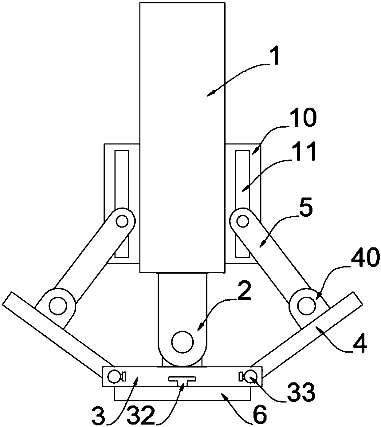
[0027] A crane for water conservancy construction, such as figure 1 As shown, it includes a cylinder 1, the lower end of the cylinder 1 is plugged with a cylinder 2, the lower end of the cylinder 2 is connected with a support plate 3, both sides of the support plate 3 are connected with side plates 4, and one side of the side plate 4 is connected There are connecting rods 5, and the bottom of the support plate 3 is provided with a backing plate 6.

[0028] In this embodiment, the cylinder 1 is a hydraulic cylinder with an inner diameter of 90 cm, an outer diameter of 112 cm, a wall thickness of 11 cm, and a weight of 27.4 kg / m.

[0029] Specifically, the supporting plate 3, the side plate 4, the connecting rod 5 and the backing plate 6 of this embodiment adopt medium-alloy medium-carbon secondary precipitation hardening ultra-high-strength steel, and the thickness is preferably 1 cm, so that it is strong enough to carry out Support work.

[0030] Further, both sides of the c...

Embodiment 2

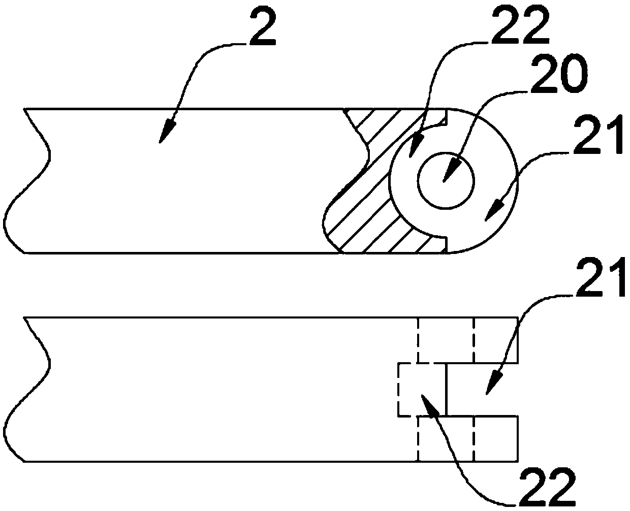
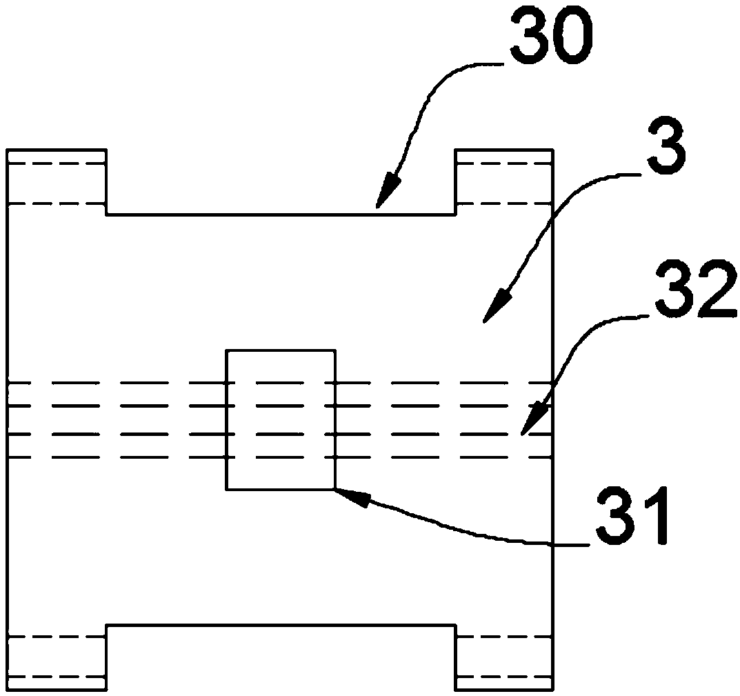
[0034] In the specific implementation, since a crane needs to be used in water conservancy construction, the crane needs hydraulic support legs to maintain balance and avoid rollover. The support plate 3 and the side plate 4 are improved, such as Figure 2-6 As shown, column holes 20 are provided on both sides of the bottom of the column body 2, a notch 21 is provided at the bottom of the column body 2, a semicircular groove 22 is provided on one side of the notch 21, and a connecting port 30 is provided at both ends of the support plate 3, The upper surface center of the support plate 3 is welded with a support block 31, one side of the support plate 3 and the lower surface are provided with a T-shaped groove 32, the upper surface of the side plate 4 is welded with a bump 40, and one side of the side plate 4 is provided with There are connection blocks 41 .

[0035] Specifically, the bottom end of the cylinder 2 is a spherical structure, and the semicircular groove 22 is hin...


PUM


Abstract

The invention relates to the technical field of crane mechanical components, in particular to a crane for water conservancy project construction. The crane comprises a cylinder barrel, a column body is inserted to the lower end of the cylinder barrel, a supporting plate is connected to the lower end of the column body, side plates are connected with the two sides of the supporting plate, one sideof each side plate is connected with a connection rod, and the bottom of the supporting plate is provided with a base plate. Column holes are formed in the two sides of the bottom end of the column body, the bottom of the column body is provided with a notch, one side of the notch is provided with a semicircular groove, and the two ends of the supporting plate are provided with connection ports. The supporting plate is hinged to the column body, the supporting plate is freely rotated, the side plates are connected to the two sides of the supporting plate, the side plates can be adjusted to theangle adapting to a site, a bolt is fixed to a fixing block so as to be rightly attached to the ground to play a supporting pole, and crane lateral turning is prevented; and site flattening is not needed, time and labor are saved, supporting is stable and firm, and early-stage preparation work of the crane is greatly simplified.

Description

technical field [0001] The invention relates to the technical field of crane mechanical parts, in particular to a crane used in hydraulic engineering construction. Background technique [0002] Crane is a kind of lifting and handling machinery widely used in ports, workshops, electric power, construction sites and other places. The name of the crane is the unified title of lifting machinery. Usually called cranes are mainly car cranes, crawler cranes and tire cranes. The usefulness of the crane lies in hoisting equipment, emergency rescue, lifting, machinery, and rescue. The crane is a common name for a crane. A working cycle includes: the pick-up device lifts the item from the pick-up place, then moves horizontally to the designated place to lower the item, and then performs a reverse movement to return the pick-up device to its original position for the next cycle. Such as fixed slewing cranes, tower cranes, truck cranes, tires, crawler cranes, etc. Among them, the out...

Claims


Application Information

Patent Timeline
Patent Type & Authority Applications(China)
IPC IPC(8): B66C23/80
CPCB66C23/80
Inventor 赵卫政黄乃佳许如安
Owner NANJING TAOTESI SOFTWARE TECH CO LTD
Why Eureka
Try Eureka