Textile soaking collector
A textile and shaft technology, applied in the field of collectors, can solve the problems of increasing the weight of textiles, reducing collection efficiency, increasing labor intensity, etc., and achieve the effects of accelerating dehydration efficiency, improving collection efficiency, and reducing labor intensity
- Summary
- Abstract
- Description
- Claims
- Application Information
AI Technical Summary
Problems solved by technology
Method used
Image

Examples
Embodiment 1
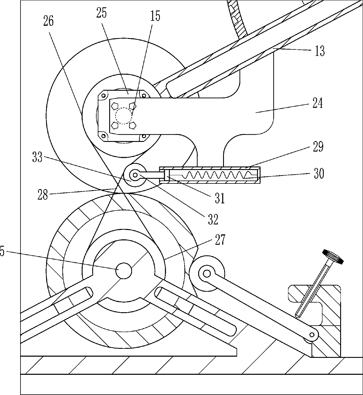
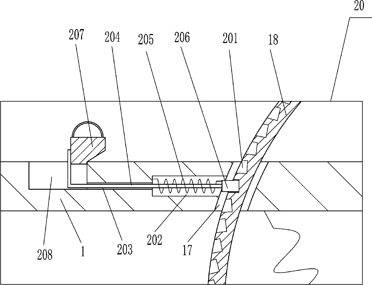
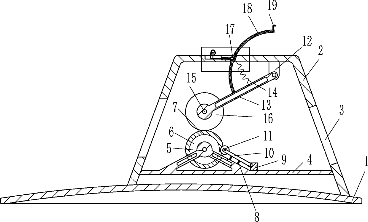
[0023] A textile immersion extractor, such as Figure 1-5As shown, it includes a base 1, a bracket 2, a support 4, a first rotating shaft 5, a first roller 6, a sponge block 7, a first spring 8, a first swing seat 9, a swing lever 10, a squeeze wheel 11, a first Two swing seats 12, the first pole 13, the second spring 14, the second rotating shaft 15, the second roller 16, the arc slide bar 18, the toggle lever 19 and the locking device 20, the right side of the base 1 top is equipped with Support 2, the left and right sides of support 2 are all opened with through hole 3, and support 4 is fixed between the lower part of left and right sides in support 2, and the left part of support 4 is connected with the first rotating shaft 5 in a rotational manner, and the first rotating shaft 5 The first roller 6 that plays a conveying role is fixed on the top, the first roller 6 is covered with a water-absorbable sponge block 7, the first swing seat 9 is fixed on the right side of the t...
Embodiment 2
[0025] A textile immersion extractor, such as Figure 1-5 As shown, it includes a base 1, a bracket 2, a support 4, a first rotating shaft 5, a first roller 6, a sponge block 7, a first spring 8, a first swing seat 9, a swing lever 10, a squeeze wheel 11, a first Two swing seats 12, the first pole 13, the second spring 14, the second rotating shaft 15, the second roller 16, the arc slide bar 18, the toggle lever 19 and the locking device 20, the right side of the base 1 top is equipped with Support 2, the left and right sides of support 2 are all opened with through hole 3, and support 4 is fixed between the lower part of left and right sides in support 2, and the left part of support 4 is connected with the first rotating shaft 5 in a rotational manner, and the first rotating shaft 5 The first roller 6 that plays a conveying role is fixed on the top, the first roller 6 is covered with a water-absorbable sponge block 7, the first swing seat 9 is fixed on the right side of the ...
Embodiment 3
[0028] A textile immersion extractor, such as Figure 1-5 As shown, it includes a base 1, a bracket 2, a support 4, a first rotating shaft 5, a first roller 6, a sponge block 7, a first spring 8, a first swing seat 9, a swing lever 10, a squeeze wheel 11, a first Two swing seats 12, the first pole 13, the second spring 14, the second rotating shaft 15, the second roller 16, the arc slide bar 18, the toggle lever 19 and the locking device 20, the right side of the base 1 top is equipped with Support 2, the left and right sides of support 2 are all opened with through hole 3, and support 4 is fixed between the lower part of left and right sides in support 2, and the left part of support 4 is connected with the first rotating shaft 5 in a rotational manner, and the first rotating shaft 5 The first roller 6 that plays a conveying role is fixed on the top, the first roller 6 is covered with a water-absorbable sponge block 7, the first swing seat 9 is fixed on the right side of the ...
PUM
 Abstract
Description
Claims
Application Information
 - R&D
- Intellectual Property
- Life Sciences
- Materials
- Tech Scout
- Unparalleled Data Quality
- Higher Quality Content
- 60% Fewer Hallucinations
Browse by: Latest US Patents, China's latest patents, Technical Efficacy Thesaurus, Application Domain, Technology Topic, Popular Technical Reports.
© 2025 PatSnap. All rights reserved.Legal|Privacy policy|Modern Slavery Act Transparency Statement|Sitemap|About US| Contact US: help@patsnap.com