A device for eliminating transmission gear clearance in a gearbox

A transmission gear and gearbox technology, which is applied in the field of gear backlash elimination, can solve problems such as the influence of the positioning accuracy of the output end, high production costs of helical gears, and unstable anti-backlash conditions, so as to achieve universal transmission conditions, reduce operating costs, and structure simple effect

Active Publication Date: 2022-01-07
CHENGDU AIRCRAFT INDUSTRY GROUP
View PDF11 Cites 0 Cited by
  • Summary
  • Abstract
  • Description
  • Claims
  • Application Information

AI Technical Summary

Problems solved by technology

However, in the case of time, due to the production process of the gear and the assembly accuracy between the gear sets, there will be errors. Therefore, when the teeth of the gear set mesh with each other, there will be a certain transmission gap between the tooth surfaces of the transmission teeth. The output end of the gearbox has high positioning accuracy requirements, and the transmission gap between the transmission teeth will have a greater impact on the positioning accuracy of the output end, resulting in insufficient positioning accuracy, especially in the field of precision transmission. Necessary and necessary to eliminate transmission gap between gear sets
The existing way to eliminate the transmission gap of the gear set generally eliminates the transmission gap through helical gear transmission, but the production cost of the helical gear is relatively high
The traditional method of eliminating the transmission gap by using spur gears is mostly to manufacture gears with materials that can be deformed and restored, compress the gears with springs or hairsprings, and magnetize the gear teeth to make the tooth surfaces of the meshing teeth fit together to achieve backlash elimination. function, but the above method still has defects such as high cost and unstable anti-backlash

Method used


Image

  • A device for eliminating transmission gear clearance in a gearbox
  • A device for eliminating transmission gear clearance in a gearbox
  • A device for eliminating transmission gear clearance in a gearbox

Examples


Embodiment 1

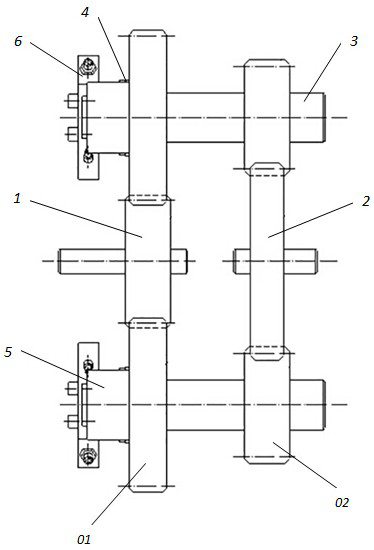
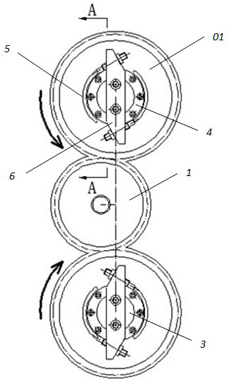
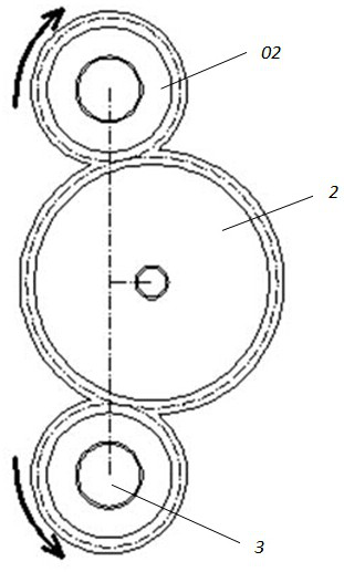
[0028] A device for eliminating transmission gear gaps in the gearbox in this embodiment, such as Figure 1-Figure 4 As shown, it includes the input gear 1 and the output gear 2, and also includes the anti-backlash shaft 3, the left end of the anti-backlash shaft 3 is set with the first anti-backlash gear 01 through the lock piece 4, and the right end of the anti-backlash shaft 3 is fixed The second anti-backlash gear 02 is sleeved; the input gear 1 meshes with two first anti-backlash gears 01 respectively, and the output gear 2 meshes with two second anti-backlash gears 02 respectively; the first anti-backlash An arc-shaped step 5 is arranged on the left end surface of the gear 01 , and an adjustment member 6 is installed on the left end of the anti-backlash shaft 3 .

[0029] Before gear transmission, it is necessary to pre-eliminate the transmission gap between the gear sets. First, loosen the locking member 4 and cancel the locking of the first anti-backlash gear 01. At th...

Embodiment 2

[0035] This embodiment is further optimized on the basis of embodiment 1, such as Figure 5 As shown, the adjustment member 6 includes an adjustment seat 61 and an adjustment bolt 62, the adjustment seat 61 is fixedly installed on the left end of the anti-backlash shaft 3, and the two ends of the adjustment seat 61 are installed with adjustment bolts 62 in reverse directions; The end surface of the adjusting bolt 62 is in contact with the side of the arc-shaped step 5 , and the axial direction of the adjusting bolt 62 is tangent to the circumference of the arc-shaped step 5 .

[0036] When it is necessary to eliminate the backlash, turn the adjusting bolt 62 installed at both ends of the adjusting seat 61, so that the end face of the adjusting bolt 62 pushes the side of the arc-shaped step 5, and the arc-shaped step 5 rotates in a circular direction under the push of the adjusting bolt 62, and manually By manipulating the screw-out or forward stroke of the adjusting bolt 62, t...

Embodiment 3

[0039] This embodiment is further optimized on the basis of the above-mentioned embodiment 1 or 2. The two ends of the adjustment seat 61 are provided with mutually parallel slopes, and the adjustment bolts 62 are installed through the slopes.

[0040] If the two ends of the adjustment seat 61 are not provided with mutually parallel slopes, in order to ensure that the axial direction of the adjustment bolt 62 is tangent to the circumference of the arc-shaped step 5, the mounting hole of the adjustment bolt 62 must be in a state close to the level, then the arc-shaped step 5 is just close to the shape of a semicircle, which causes the installation position of the adjustment bolt 62 to be very narrow this time, which is unfavorable for manual operation of the adjustment bolt 62. Therefore, in order to ensure that the axial direction of the adjusting bolt 62 is tangent to the circumference where the arc-shaped step 5 is located, the stroke space of the adjusting bolt 62 is as larg...


PUM


Abstract

The invention discloses a device for eliminating backlash of transmission gears in a gearbox, which includes an input gear and an output gear, and an anti-backlash shaft. The left end of the anti-backlash shaft is provided with a first anti-backlash gear through a locking piece. The right end of the backlash shaft is fixedly sleeved with a second anti-backlash gear; the input gears are respectively meshed with two first anti-backlash gears, and the output gears are respectively meshed with two second anti-backlash gears; There is an arc-shaped step on the left end surface of the gear, and an adjusting piece is installed on the left end of the anti-backlash shaft. Backlash function; the present invention has simple structure, convenient disassembly and assembly, greatly reduced operating costs, stable backlash elimination, manual adjustable backlash elimination, universal application to various transmission situations, linkage anti-backlash, forward and reverse backlash elimination, and effective guarantee of anti-backlash The beneficial effect of gap precision.

Description

technical field [0001] The invention belongs to the technical field of gear backlash elimination, and in particular relates to a device for eliminating the backlash of transmission gears in a gear box. Background technique [0002] In the field of transmission in the mechanical gearbox of CNC machine tools, it is often necessary to reduce the output speed of the gearbox to achieve high torque output. The deceleration of the output speed of the gearbox is achieved through the meshing transmission of a specific reduction ratio between the gear sets inside the gearbox. Ideally, the transmission ratio between the gears is fixed, that is, the gear set The speed after deceleration is also constant. However, in the case of time, due to the production process of the gear and the assembly accuracy between the gear sets, there will be errors. Therefore, when the teeth of the gear set mesh with each other, there will be a certain transmission gap between the tooth surfaces of the tran...

Claims


Application Information

Patent Timeline
Patent Type & Authority Patents(China)
IPC IPC(8): F16H57/12
CPCF16H57/12
Inventor 张强黄中平
Owner CHENGDU AIRCRAFT INDUSTRY GROUP
Why Eureka
Try Eureka