Vehicle positioning method, automatic driving control method and related systems
A technology for automatic driving control and vehicle positioning, applied in the field of intelligent transportation, can solve problems such as driving, achieve high accuracy, avoid driving inconvenience or driving accidents, and improve the accuracy of vehicle positioning.
- Summary
- Abstract
- Description
- Claims
- Application Information
AI Technical Summary
Problems solved by technology
Method used
Image
Examples
no. 1 example
[0063] see figure 1 , which is a flowchart of a vehicle positioning method provided in an embodiment of the present application.
[0064] like figure 1 As shown, the vehicle positioning method provided in this embodiment includes:
[0065] Step 101: Obtain the position information of the wheels of the vehicle by using the laser radar installed in the parking lot.
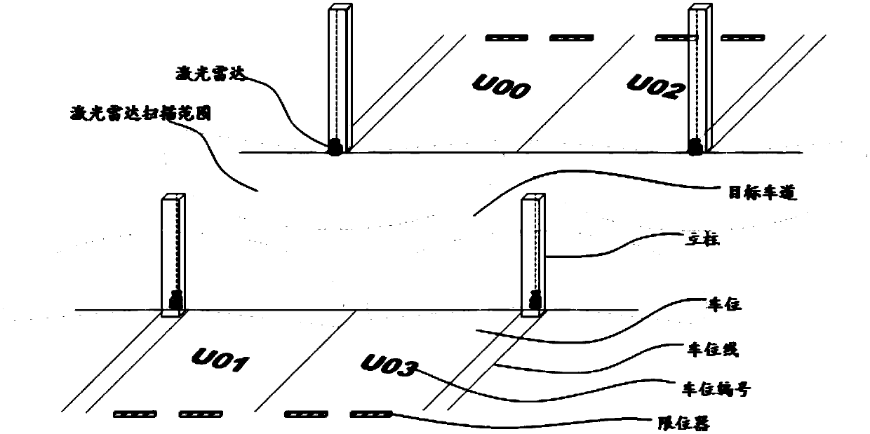
[0066] There are usually multiple lanes and multiple parking spaces distributed in the parking lot. Lanes may be in various forms, such as straight roads, curves, or up and down ramps. Regardless of whether it is an indoor or outdoor parking lot, there are usually buildings, such as walls, columns, etc., near the driveway and the parking space.
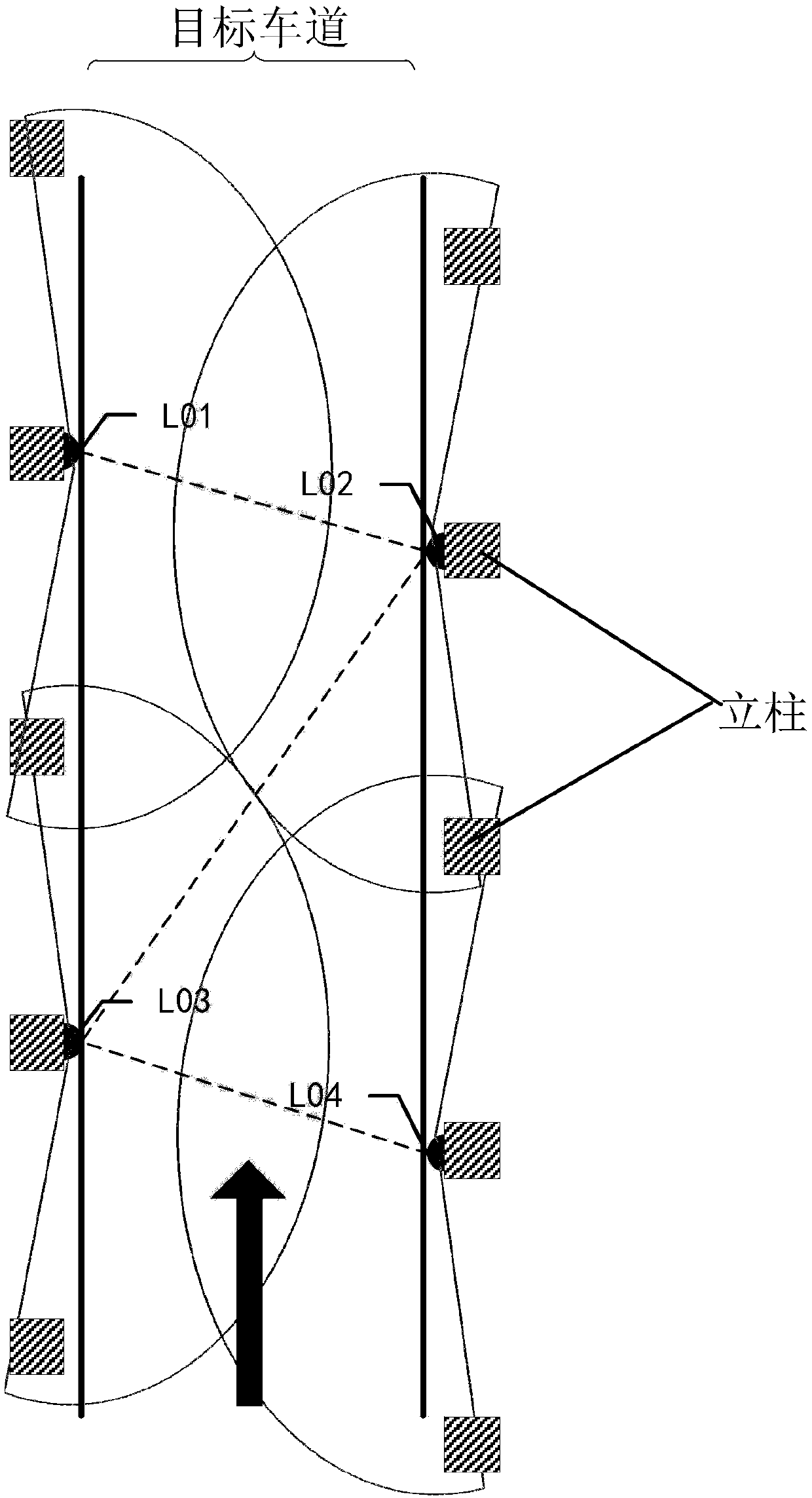
[0067] In this embodiment, a plurality of laser radars may be pre-installed at the bottom of the building on both sides of each lane of the parking lot. As a specific implementation, multiple laser radars can be arranged at the bottom of the building according to the p...
no. 2 example
[0083] see Figure 4 , which is a flow chart of another vehicle positioning method provided by the embodiment of the present application.
[0084] like Figure 4 As shown, the vehicle positioning method provided in this embodiment includes:
[0085] Step 401: Using the laser radar to transmit detection signals to the wheels of the vehicle, and using the laser radar to receive signals reflected back by the wheels.
[0086] In this embodiment, the setting method of the laser radar in the parking lot is the same as that in the foregoing embodiments, and will not be repeated here. For the relevant description about the setting manner of the laser radar, reference may be made to the foregoing embodiments.
[0087] In practical applications, the laser radar converts electrical pulses into optical pulses and emits them. Therefore, the optical signal emitted by the laser radar is the detection signal. When the pulsed laser emitted by the lidar hits the wheel, causing scattering, a...
no. 3 example
[0109] see Figure 6 , which is a flowchart of an automatic driving control method provided in this embodiment.
[0110] Such as Figure 6 As shown, the automatic driving control method provided in this embodiment includes:
[0111] Step 601: Obtain the position of the vehicle.
[0112] It should be noted that, in this embodiment, step 601 is specifically to obtain the position of the vehicle according to the vehicle positioning method provided in the aforementioned first embodiment or the second embodiment. For the implementation process of this step, reference may be made to the foregoing embodiments, and details are not repeated here.
[0113] Step 602: Obtain the planned path of the vehicle in the parking lot.
[0114] This step provides two ways to obtain the planned path, and these two ways are respectively aimed at the situation of controlling the vehicle to automatically park into and automatically park out of the parking lot. The implementation of this step will ...
PUM
 Abstract
Description
Claims
Application Information
 - R&D
- Intellectual Property
- Life Sciences
- Materials
- Tech Scout
- Unparalleled Data Quality
- Higher Quality Content
- 60% Fewer Hallucinations
Browse by: Latest US Patents, China's latest patents, Technical Efficacy Thesaurus, Application Domain, Technology Topic, Popular Technical Reports.
© 2025 PatSnap. All rights reserved.Legal|Privacy policy|Modern Slavery Act Transparency Statement|Sitemap|About US| Contact US: help@patsnap.com


