

Surgical operating knife blade sharpness qualification detection device
A surgical blade and detection device technology, applied in the direction of testing machinability, can solve the problems of inaccurate test results, inconvenient recording and testing process, etc., and achieve the effect of reducing workload
- Summary
- Abstract
- Description
- Claims
- Application Information
AI Technical Summary
Problems solved by technology
Method used
Image

Examples
Embodiment 1
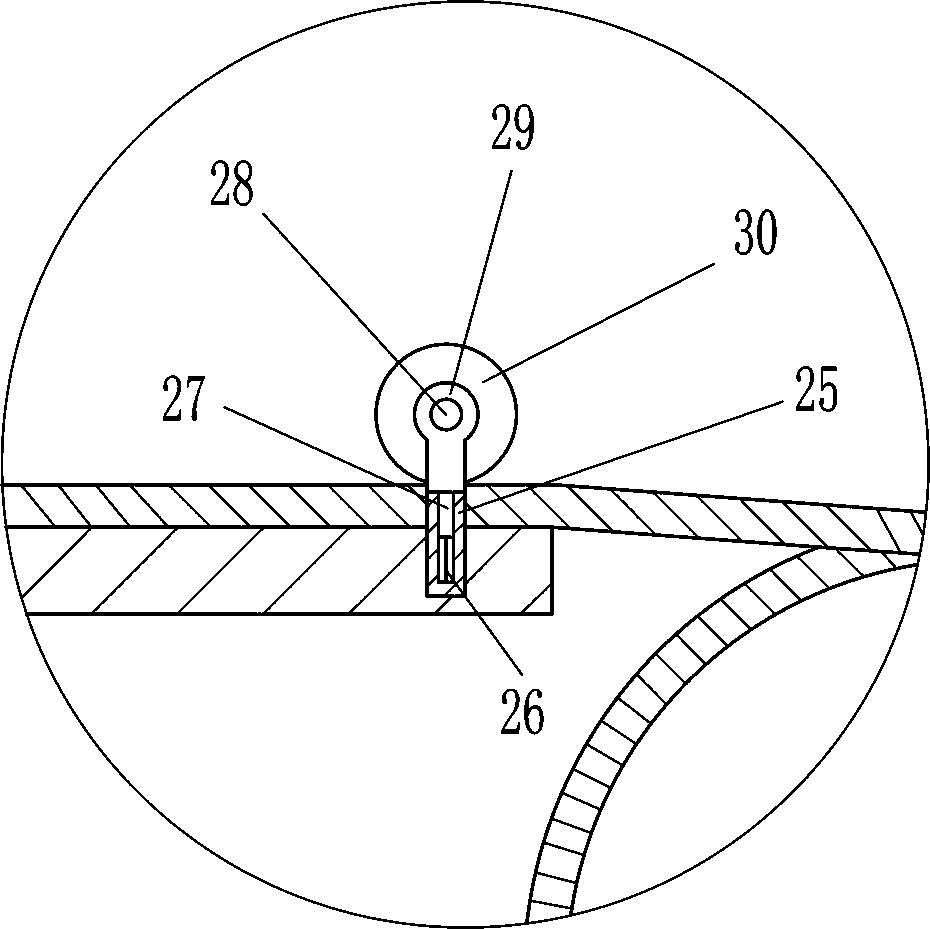
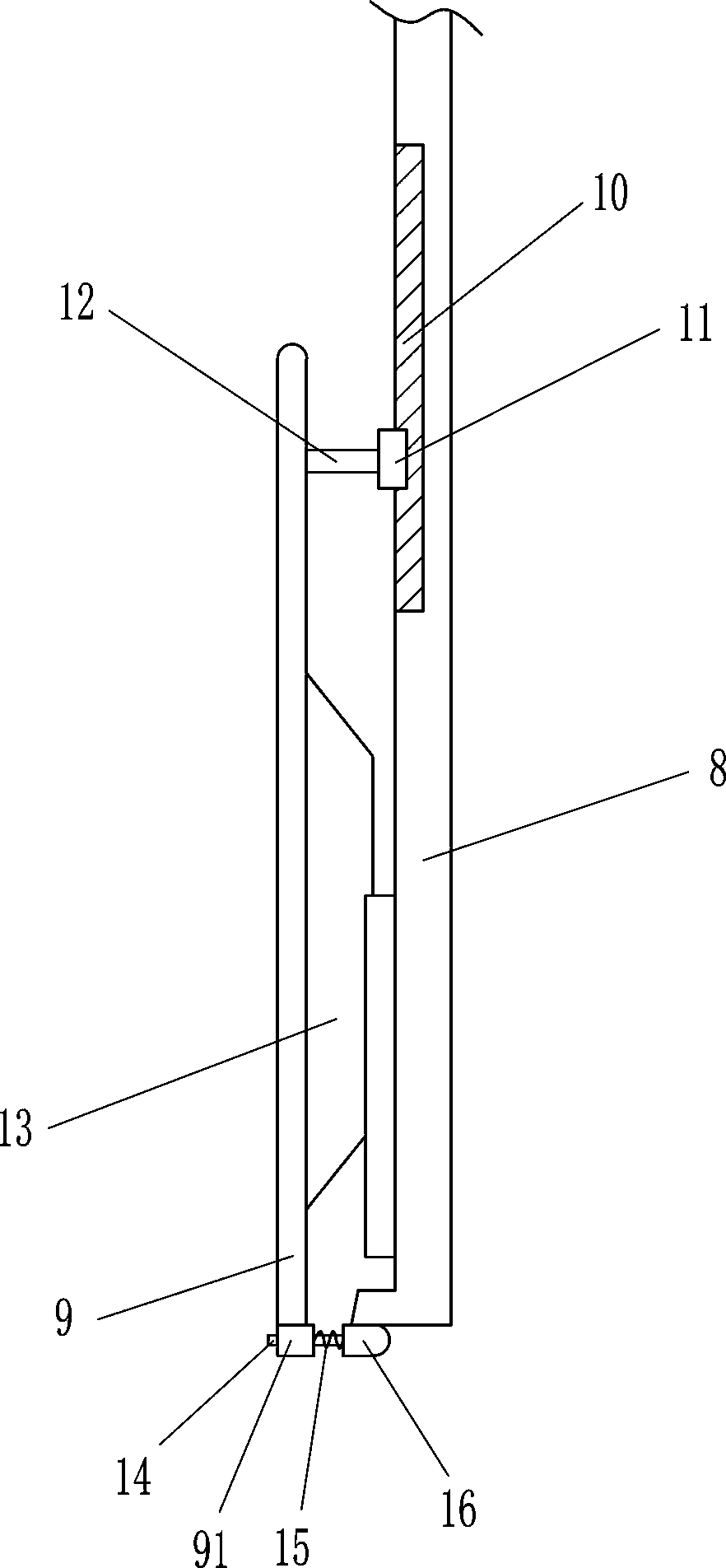
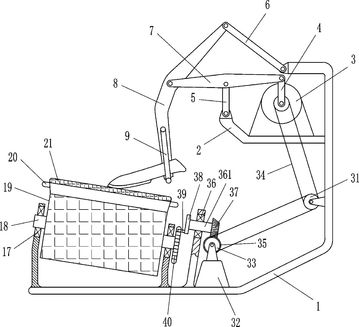
[0018] A surgical blade sharpness qualified detection device, such as Figure 1-4As shown, it includes a mounting frame 1, an L-shaped connecting rod 2, a motor 3, a first connecting rod 4, a second connecting rod 5, a third connecting rod 6, a fourth connecting rod 7, an arc-shaped connecting rod 8, the first Pressure rod 9, guide sleeve 91, slide rail 10, slider 11, first pole 12, rubber pressure block 13, second pole 14, compression spring 15, limit block 16, first bearing seat 17, first Rotating shaft 18, waste material drum 19, support plate 20, class skin material 21, bracing frame 22 and new material drum 23, the upper left side of installation frame 1 is provided with L-shaped connecting rod 2, and the top right side of L-shaped connecting rod 2 is provided with There is a motor 3, the output shaft of the motor 3 is connected with a first connecting rod 4, the left end of the L-shaped connecting rod 2 is hingedly connected with a second connecting rod 5, and the top en...
Embodiment 2
[0020] A surgical blade sharpness qualified detection device, such as Figure 1-4 As shown, it includes a mounting frame 1, an L-shaped connecting rod 2, a motor 3, a first connecting rod 4, a second connecting rod 5, a third connecting rod 6, a fourth connecting rod 7, an arc-shaped connecting rod 8, the first Pressure rod 9, guide sleeve 91, slide rail 10, slider 11, first pole 12, rubber pressure block 13, second pole 14, compression spring 15, limit block 16, first bearing seat 17, first Rotating shaft 18, waste material drum 19, support plate 20, class skin material 21, bracing frame 22 and new material drum 23, the upper left side of installation frame 1 is provided with L-shaped connecting rod 2, and the top right side of L-shaped connecting rod 2 is provided with There is a motor 3, the output shaft of the motor 3 is connected with a first connecting rod 4, the left end of the L-shaped connecting rod 2 is hingedly connected with a second connecting rod 5, and the top e...
Embodiment 3
[0023] A surgical blade sharpness qualified detection device, such as Figure 1-4 As shown, it includes a mounting frame 1, an L-shaped connecting rod 2, a motor 3, a first connecting rod 4, a second connecting rod 5, a third connecting rod 6, a fourth connecting rod 7, an arc-shaped connecting rod 8, the first Pressure rod 9, guide sleeve 91, slide rail 10, slider 11, first pole 12, rubber pressure block 13, second pole 14, compression spring 15, limit block 16, first bearing seat 17, first Rotating shaft 18, waste material drum 19, support plate 20, class skin material 21, bracing frame 22 and new material drum 23, the upper left side of installation frame 1 is provided with L-shaped connecting rod 2, and the top right side of L-shaped connecting rod 2 is provided with There is a motor 3, the output shaft of the motor 3 is connected with a first connecting rod 4, the left end of the L-shaped connecting rod 2 is hingedly connected with a second connecting rod 5, and the top e...
PUM
 Abstract
Description
Claims
Application Information