
In-situ X-ray CT imaging device for neutron diffraction spectrometer

A CT imaging and X-ray technology, applied in the direction of using wave/particle radiation, material analysis using wave/particle radiation, measuring devices, etc., can solve problems such as the inability to meet residual stress and internal defect expansion

Pending Publication Date: 2019-04-09
CENT OF EXCELLENCE FOR ADVANCED MATERIALS +1
View PDF0 Cites 7 Cited by
  • Summary
  • Abstract
  • Description
  • Claims
  • Application Information

AI Technical Summary

Problems solved by technology

[0004] In order to overcome the deficiencies in the prior art, one of the purposes of the present invention is to provide an in-situ X-ray CT imaging device for neutron diffraction spectrometers, which can solve the problem of simultaneous residual stress, Problems with the measurement requirements of internal defects and expansion

Method used


Image

  • In-situ X-ray CT imaging device for neutron diffraction spectrometer
  • In-situ X-ray CT imaging device for neutron diffraction spectrometer
  • In-situ X-ray CT imaging device for neutron diffraction spectrometer

Examples


Embodiment Construction

[0027] Below, the present invention will be further described in conjunction with the accompanying drawings and specific implementation methods. It should be noted that, under the premise of not conflicting, the various embodiments described below or the technical features can be combined arbitrarily to form new embodiments. .

[0028] It should be noted that when a component is said to be "fixed" to another component, it can be directly on the other component or there can also be an intervening component. When a component is said to be "connected" to another component, it may be directly connected to the other component or there may be intervening components at the same time. When a component is said to be "set on" another component, it may be set directly on the other component or there may be an intervening component at the same time. The terms "vertical," "horizontal," "left," "right," and similar expressions are used herein for purposes of illustration only.

[0029] Un...


PUM


Abstract

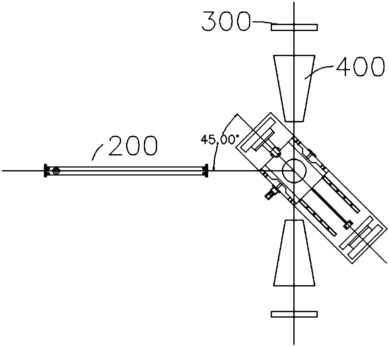
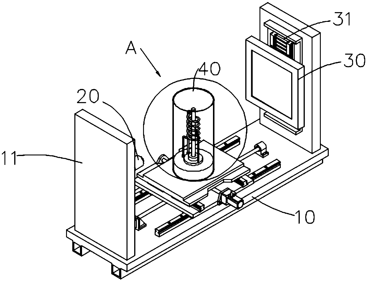
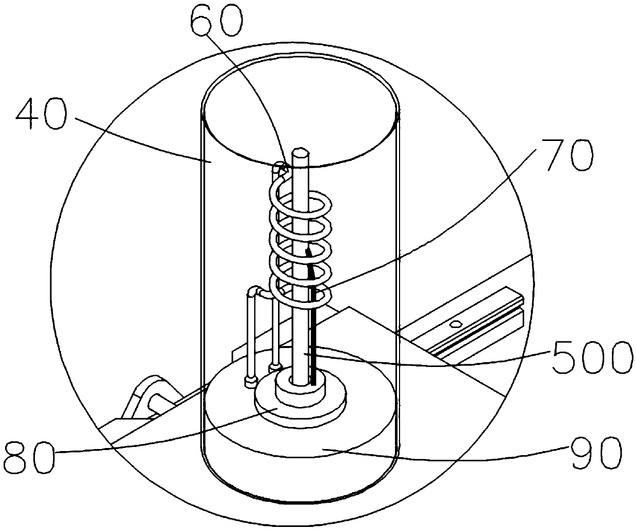
The invention discloses an in-situ X-ray CT imaging device for a neutron diffraction spectrometer. The in-situ X-ray CT imaging device comprises a fixed seat, a nanometer focus X-ray tube, an X-ray detector, a sealing container and a movable structure; the nanometer focus X-ray tube and the X-ray detector are arranged at two opposite sides of the fixed seat; the movable structure is arranged at the fixed seat in a sliding manner, the sealing container is arranged at the mobile structure, a sample is held in the sealing container, a neutron generator produces a neutron beam, and an included angle between an axis of the neutron beam and the axis of the nanometer focus X-ray tube is 45 DEG, the X-ray penetrates the sample and is detected by the X-ray detector, thereby performing real-time three-dimensional imaging on the sample. The simultaneous performing of the X-ray imaging and the neutron stress measurement can be satisfied, the mutual interference is avoided, expansion size and internal defects of the sample can be measured through the X-ray imaging technology, and the non-contact expansion factor measurement and the real-time internal defect measurement are realized.

Description

technical field [0001] The invention relates to the field of neutron diffraction, in particular to an in-situ X-ray CT imaging device for a neutron diffraction spectrometer. Background technique [0002] At present, with the development and progress of science and technology, in-situ tests of metal materials are gradually promoted. In-situ tests of metal materials usually need to be carried out at high or low temperatures, such as measuring expansion coefficient, internal stress, phase transition, etc. In order to establish the relationship between the properties of metal materials, internal residual stress, and microscopic defects, it is usually necessary to take multiple tests separately. When in-situ stress measurement and expansion coefficient determination are performed on the same sample, the identity of the measurement position cannot be guaranteed, and the expansion coefficient or internal microstructure of the sample will change due to heating twice. Therefore, it ...

Claims


Application Information

Patent Timeline
IPC IPC(8): G01N23/046G01B15/00G01L1/25
CPCG01B15/00G01L1/25G01N23/046
Inventor 贡志锋詹霞马艳玲张书彦高建波初铭强山乔帕德
Owner CENT OF EXCELLENCE FOR ADVANCED MATERIALS
Learn More