Measuring device and method for optical element damage threshold under vacuum environment

A technology of optical components and damage threshold, which is applied in the direction of testing optical performance, etc., can solve the problems of optical component measurement reliability reduction, no spot quality monitoring, spot area difference, etc., to achieve accurate measurement, high accuracy, and strong functions Effect

Active Publication Date: 2017-06-13
SHANGHAI INST OF OPTICS & FINE MECHANICS CHINESE ACAD OF SCI
View PDF5 Cites 9 Cited by
  • Summary
  • Abstract
  • Description
  • Claims
  • Application Information

AI Technical Summary

Problems solved by technology

Such measurement methods all measure the spot area of ​​the measuring beam in the atmospheric environment and then measure the damage threshold. There are two problems in this measuring device and method: 1) the transmission of the light beam in the vacuum environment and the transmission in the atmospheric environment There is a difference, that is, there is a difference in the spot area measured in the vacuum environment and the atmospheric environment; 2) The quality of the spot in the vacuum environment is not monitored during the measurement process, which will inevitably lead to a decrease in the reliability of the measurement of the damage threshold of the optical element

Method used


Image

  • Measuring device and method for optical element damage threshold under vacuum environment
  • Measuring device and method for optical element damage threshold under vacuum environment
  • Measuring device and method for optical element damage threshold under vacuum environment

Examples


Embodiment

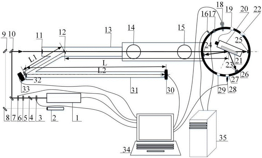
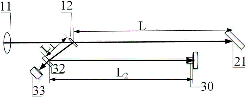
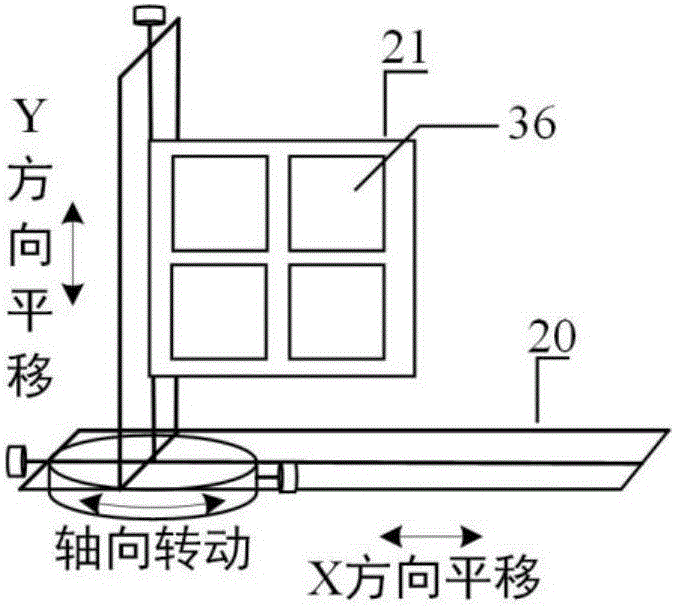
[0040] Example: see figure 1 , figure 2 and image 3 , figure 1 It is a schematic diagram of the laser damage threshold measurement device in vacuum environment of the present invention. In the figure, 1 is the measurement laser, 2 is the He-Ne laser, 3 is the 1 / 2 wave plate, 4 is the polarizer, 5 is the 1 / 2 wave plate, 6 is the electronic shutter, 7 and 10 are the measuring beam mirrors, 8 and 9 are He-Ne optical reflectors, 11 is a focusing lens, 12 is a beam splitter, 13 is a main beam transmission pipe for measurement, 14 is a molecular pump interface, 15 is an ion pump interface, 16 is a low vacuum gauge, and 17 is a high vacuum gauge , 18 is the residual gas analyzer, 19 is the three-dimensional mobile platform control cable interface, 20 is the three-dimensional mobile platform, 21 is the sample fixture to be tested, 22 is the spare interface, 23, 24 and 25 are energy absorbing materials, 26 is the measurement room Cavity, 27 is a monitoring window, 28 is a CCD sys...


PUM


Abstract

The invention discloses a measuring device and method for an optical element damage threshold under the vacuum environment. By adopting an equivalent light path, accurate measurement of a facula area and the facula quality in the measuring process under the vacuum environment are monitored in real time, and accurate measurement of the optical element damage threshold is ensured. The device can perform damage threshold measurement on four transmission and reflection elements and diffraction element samples under the vacuum environment at a time in 1-on-1, S-on-1, R-on-1 and raster scanning modes, and residual gas in the testing environment can be analyzed. The equipment can automatically control the measuring process and achieve automatic data collection, and the damage testing efficiency of the optical element under the vacuum environment is greatly improved.

Description

technical field [0001] The invention relates to the measurement of the damage threshold of an optical element, in particular to a measuring device and a method for measuring the damage threshold of an optical element in a vacuum environment. Background technique [0002] Optical components, as basic components in optical systems, are widely used in high-power laser systems, laser weapons, and laser processing. As people continue to increase the output energy of lasers, the laser damage threshold of optical components has become a bottleneck for the further development of ultra-high-energy lasers. In order to deeply study the damage performance and generation mechanism of optical components, accurately evaluate the laser damage resistance of optical components, develop and improve the laser damage threshold measurement technology of optical components, so as to guide the optimization and improvement of the optical component preparation process. [0003] With the wide applica...

Claims


Application Information

Patent Timeline
Patent Type & Authority Applications(China)
IPC IPC(8): G01M11/02
CPCG01M11/02
Inventor 晋云霞孔钒宇李大伟赵元安邵建达张益彬黄昊鹏王勇禄陈鹏陈俊明徐姣
Owner SHANGHAI INST OF OPTICS & FINE MECHANICS CHINESE ACAD OF SCI
Why Eureka
Try Eureka