

Power equipment maintenance and transportation lifting device
A lifting device and power equipment technology, applied in the direction of lifting devices, lifting frames, switchgear, etc., can solve the problems of no protection measures for power equipment, heavy placement of power equipment, and prone to safety accidents, so as to avoid accidents and reduce Maintenance cost, effect of increased gripping and guarding functions
- Summary
- Abstract
- Description
- Claims
- Application Information
AI Technical Summary
Problems solved by technology
Method used
Image

Examples
Embodiment 1
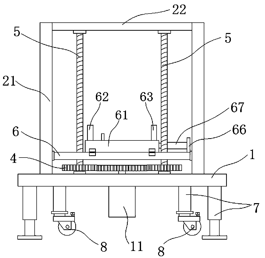
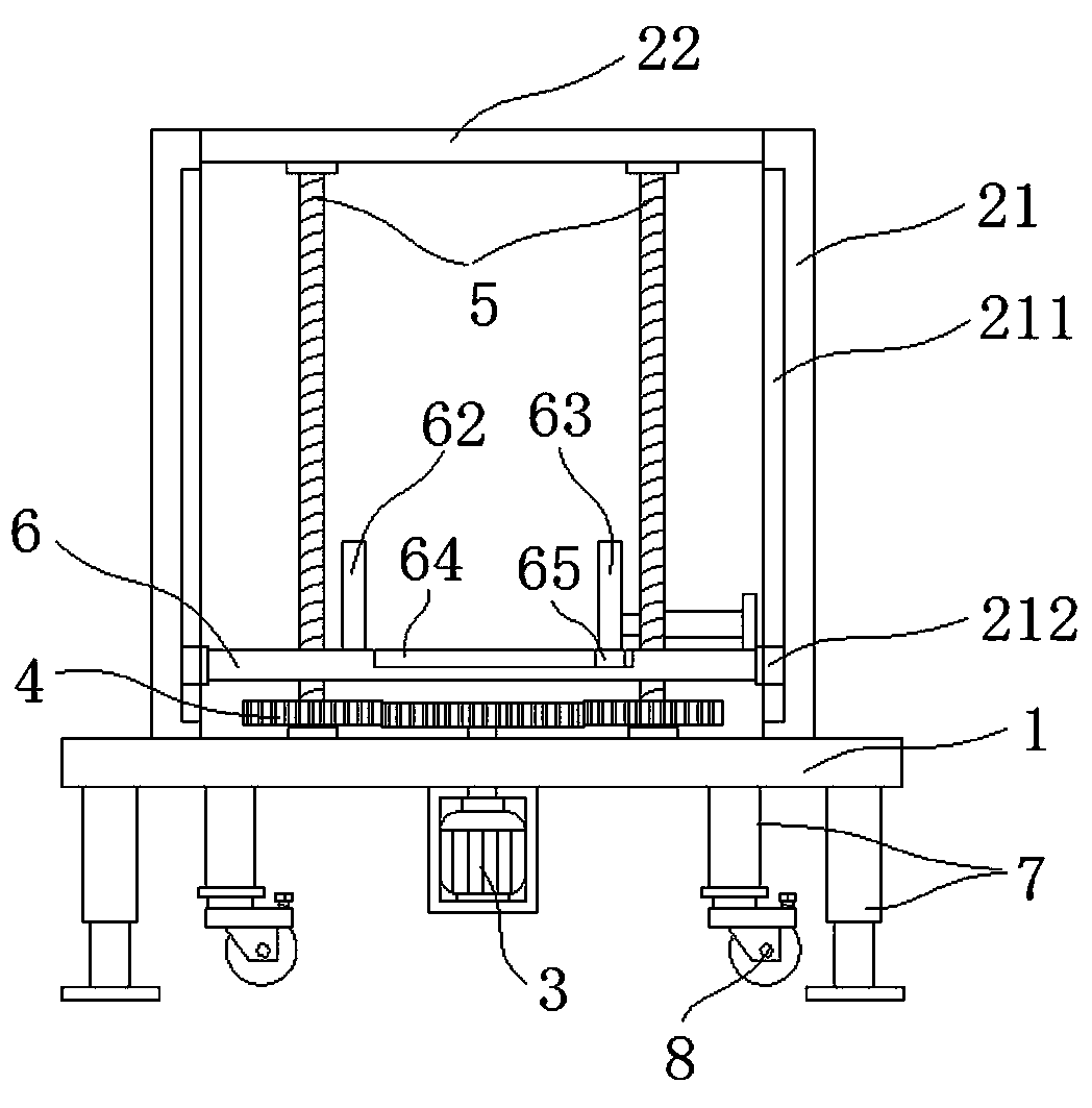
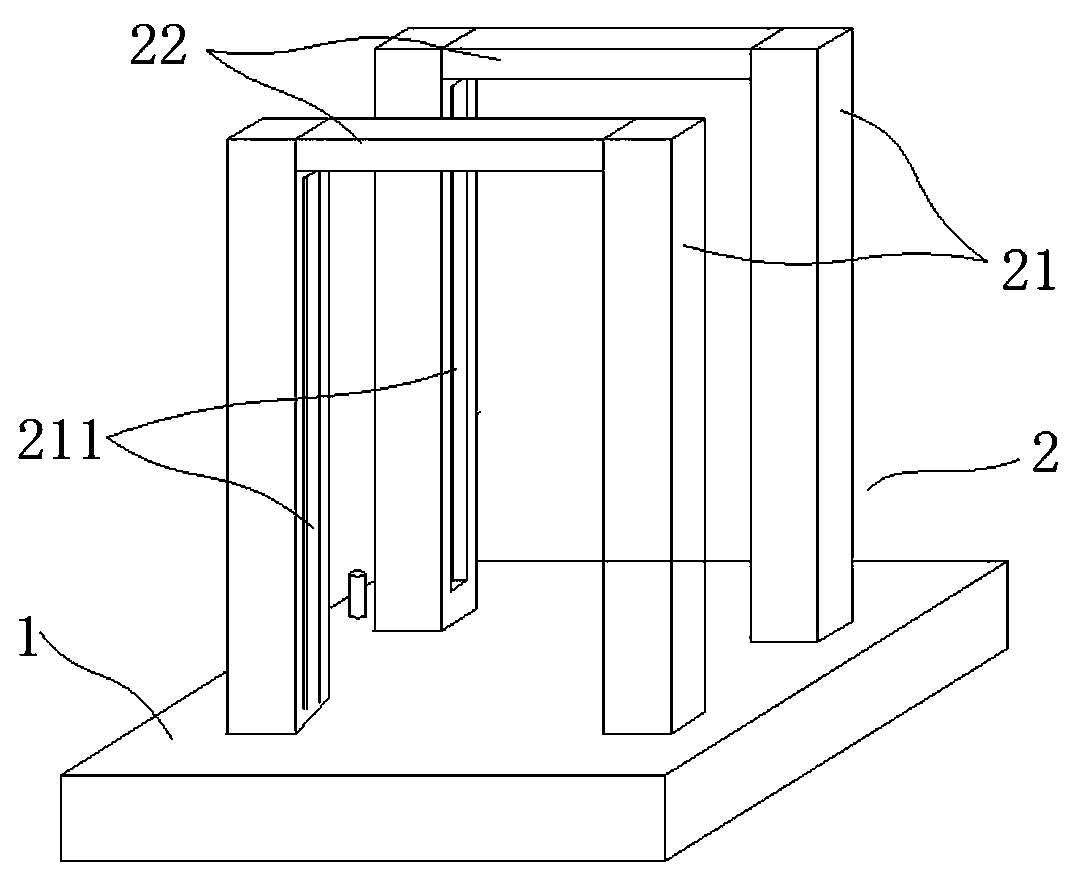
[0021] Such as figure 1 As shown, a lifting device for maintenance and transportation of electrical equipment includes a base 1, a support frame 2, a motor 3, a transmission gear 4, at least two screw rods 5, and a loading plate 6. The support frame 2 is fixed on the base 1, and the screw rod 5 is vertical. One end is rotatably connected to the base 1, and the other end is rotatably connected to the support frame 2; the loading plate 6 is provided with a mounting hole corresponding to the screw 5, and the loading plate 6 is connected to the screw 5 through the mounting hole; the motor 3 Fixed on the base 1, the transmission gear 4 is connected with the screw rod 5 and the motor 3 respectively. A protective box 11 is provided at the bottom of the base 1 , and the motor 3 is provided inside the protective box 11 . The motor 3 is arranged in the protective box 11, which can protect the motor 3, and can also prevent the operator from accidentally touching the motor 3, which may c...
Embodiment 2
[0029] This embodiment has the same structure as the other parts of the embodiment 1, except that the bottom of the base 1 is also provided with a liftable leg 7 composed of a hydraulic cylinder. The lifting motion of the entire base 1 can be realized by the hydraulic cylinder, and the height of the base 1 can be adjusted according to the needs of the site, so that the equipment can be moved away from the loading plate 6 or put on the loading plate 6. The bottoms of two adjacent legs 7 are connected with universal wheels 8, and connected with the universal wheels 8 are brake pads for limiting the rotation of the universal wheels 8; the bottoms of the other two legs 7 are provided with pads. When the whole device needs to be moved, the brake pads are opened, the whole device is slightly tilted, and the other two supporting feet 7 are lifted off the ground, thereby realizing the movement of the whole device; when not moving, the brake pads are then locked.
PUM
 Abstract
Description
Claims
Application Information