
Generation method of line synchronization signal, projection component, projector and storage medium

A frame synchronization signal and line synchronization technology, which is applied to color TV components, image reproducers using projection devices, electrical components, etc., can solve problems such as the influence of line synchronization signals, and achieve avoidance of phase shift effects, accuracy and stability Effect of Line Sync Signal

Active Publication Date: 2021-06-01
GOERTEK OPTICAL TECH CO LTD
View PDF4 Cites 0 Cited by
  • Summary
  • Abstract
  • Description
  • Claims
  • Application Information

AI Technical Summary

Problems solved by technology

[0004] The main purpose of the present invention is to provide a method for generating a line synchronous signal, a laser projection component, a laser projector, and a computer-readable storage medium, which effectively solves the problem of the received sinusoidal signal due to changes in frequency or amplitude. Problems with Synchronous Signals Affecting

Method used


Image

  • Generation method of line synchronization signal, projection component, projector and storage medium
  • Generation method of line synchronization signal, projection component, projector and storage medium
  • Generation method of line synchronization signal, projection component, projector and storage medium

Examples


Embodiment Construction

[0043]It should be understood that the specific embodiments described herein are merely intended to illustrate the invention and are not intended to limit the invention.

[0044]The present invention provides a method of generating a row synchronization signal, by using the sinusoidal signal output feedback of the MEMS microcomputer system through the filter amplification and analog to digital conversion as a row synchronization signal in the horizontal direction of the laser light, so that the drive circuit is avoided. The phase shift effect caused by the MEMS resonance state is effectively solved the problem of the received sinusoidal signal due to frequency changes or amplitude changes, and the problem of affecting the row synchronization signal makes real-time, accurate and stable row synchronization signals, thus Each project module is guaranteed to work normally.

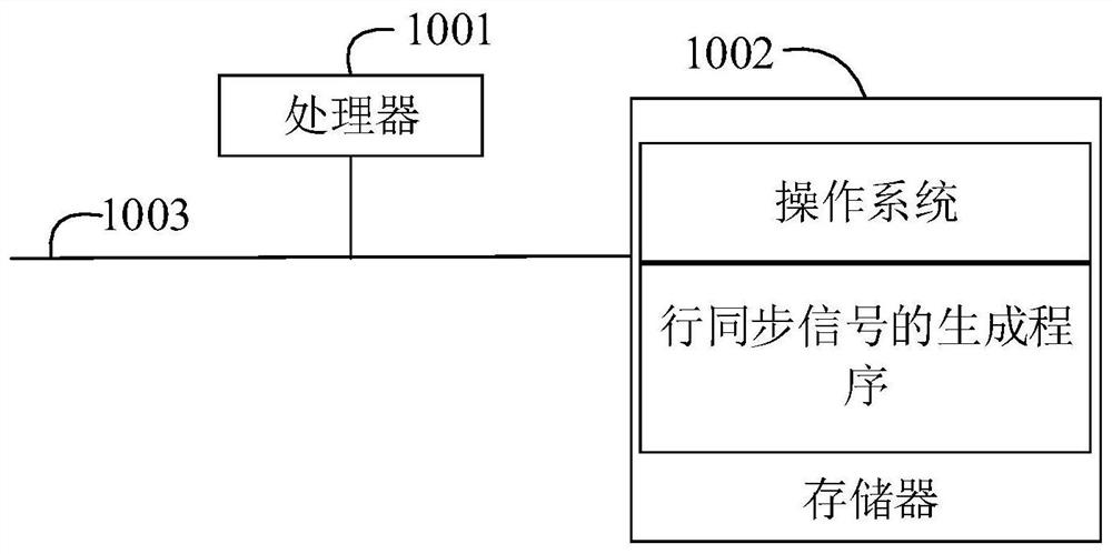
[0045]Such asfigure 1 Distancefigure 1 It is a schematic diagram of the hardware operating environment of the embodimen...


PUM


Abstract

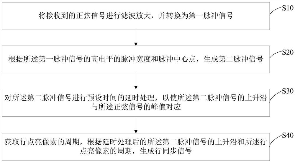
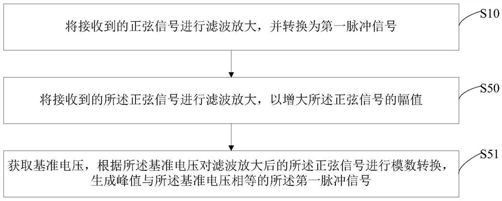
The invention discloses a method for generating a horizontal synchronous signal, comprising the following steps: filtering and amplifying the received sinusoidal signal, and converting it into a first pulse signal; according to the pulse width of the high level of the first pulse signal and Pulse center point, generate a second pulse signal; perform delay processing for a preset time on the second pulse signal, so that the rising edge of the second pulse signal corresponds to the peak value of the sinusoidal signal; obtain row lighting The cycle of the pixel generates a row synchronous signal according to the rising edge of the delayed second pulse signal and the cycle of lighting up the pixel in the row. The invention also discloses a laser projection assembly, a laser projector and a computer-readable storage medium. The invention effectively solves the problem that the received sinusoidal signal affects the generation of the line synchronous signal due to the frequency change or the amplitude change.

Description

Technical field[0001]The present invention relates to the field of data signal communication, and more particularly to a method of generating a row synchronization signal, a laser projection assembly, a laser projector, and a computer readable storage medium.Background technique[0002]With the development of projection technology, the laser beam scanning projector (LBS) has a simple structure, small size, low optical road loss, low power consumption, wide color, high contrast, high resolution, and no focus, becomes more and more It is favored by the market.[0003]In the existing laser projection technique, the three primary color laser beam is projected to the light screen imagery by a mirror of the microelectromechanical system (MEMS), wherein the sinusoidal signal obtained by driving the mirror with a horizontal drive signal is used as a laser The line synchronization signal, in general, since the sine wave signal employed by the row synchronization signal of the laser, the frequenc...

Claims


Application Information

Patent Timeline
Patent Type & Authority Patents(China)
IPC IPC(8): H04N9/31
CPCH04N9/3141H04N9/3155H04N9/3161
Inventor 高文刚
Owner GOERTEK OPTICAL TECH CO LTD
Learn More