Floor brush module and dust collector

A component and roller brush technology, which is applied to vacuum cleaners, suction nozzles, cleaning equipment, etc., can solve the problems of rising cost, high load, and no ash suction effect, and achieve the effect of ensuring air tightness and reducing motor costs.

Pending Publication Date: 2019-04-12
SKYBEST ELECTRIC APPLIANCE SUZHOU CO LTD
View PDF0 Cites 1 Cited by
  • Summary
  • Abstract
  • Description
  • Claims
  • Application Information

AI Technical Summary

Problems solved by technology

[0002] At present, the common double-roller floor brushes on the market often do not have a specific adjustment for changes in the working environment (floor/carpet) to achieve a better dust absorption effect.
In addition, compared with the single-roller brush str

Method used


Image

  • Floor brush module and dust collector
  • Floor brush module and dust collector
  • Floor brush module and dust collector

Examples


Embodiment Construction

[0044]The present invention will be described in detail below in conjunction with specific embodiments shown in the accompanying drawings. However, these embodiments do not limit the present invention, and any structural, method, or functional changes made by those skilled in the art according to these embodiments are included in the protection scope of the present invention.

[0045] It should be understood that in the description of specific embodiments of the present invention, terms such as "first" and "second" are used for description purposes only, and cannot be understood as indicating or implying relative importance or implicitly indicating the indicated technology number of features. Thus, a feature defined as "first" or "second" may explicitly or implicitly include one or more of these features.

[0046] In the specific implementation of the present invention, unless otherwise clearly stipulated and limited, terms such as "connected" and "connected" should be unders...


PUM


Abstract

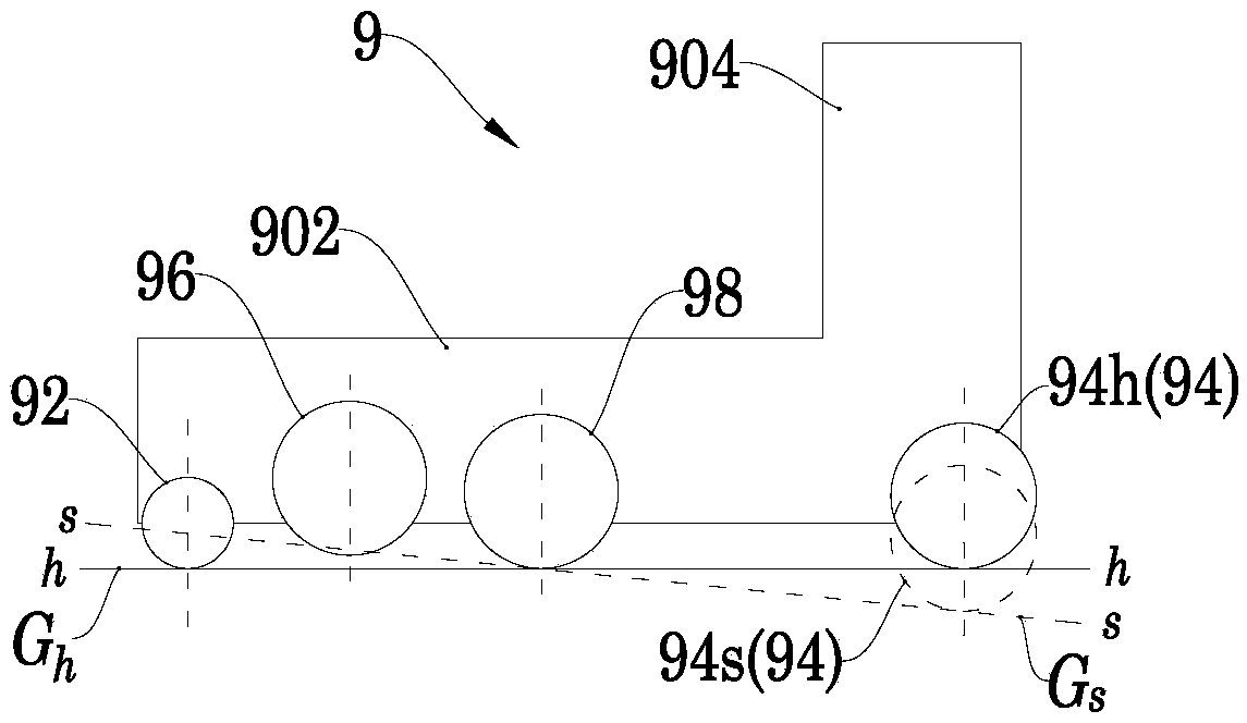
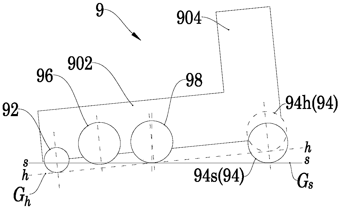
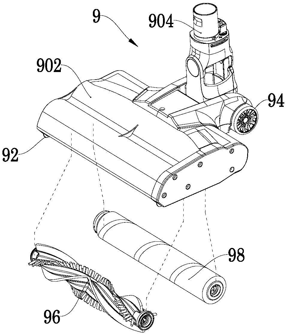
The invention discloses a floor brush module. The floor brush module comprises a floor brush body; a front support wheel, a front rolling brush, a back rolling brush and a back support shell are orderly arranged on the floor brush body from front to back; the floor brush module is constructed to possess a first working state and a second working state adapted to different to-be-cleaned faces; whenthe floor brush module is at the first working state, the front support wheel and the back support wheel in a high state are supported on the surface of the first to-be-cleaned face; when the floor brush module is at the second working state, the front support wheel is sunken into the second to-be-cleaned face, the back support wheel in a low state is supported on the surface of the second to-be-cleaned face; the difference between the distance from the back rolling brush to the surface of the first to-be-cleaned face in the first working state and the distance from the back rolling brush tothe surface of the second to-be-cleaned face is not more than 1/50 of the semi-diameter of the back rolling brush. The floor brush module not only can reduce the motor cost of the back rolling brush,but also can guarantee the airtightness adjacent to a sucker. The invention further discloses a dust collector.

Description


Claims


Application Information

Patent Timeline
Owner SKYBEST ELECTRIC APPLIANCE SUZHOU CO LTD
Why Eureka
Try Eureka