
Asymmetrical exhaust structure of lift fan

A lift fan, asymmetric technology, used in aircraft parts, propellers, aircraft and other directions, can solve problems affecting lift fan performance, performance loss, etc., to ensure nozzle performance and fan aerodynamic performance, and reduce exhaust loss.

Inactive Publication Date: 2019-04-12
AECC SHENYANG ENGINE RES INST
View PDF7 Cites 3 Cited by
  • Summary
  • Abstract
  • Description
  • Claims
  • Application Information

AI Technical Summary

Problems solved by technology

The discontinuous structure of the adapter casing or the aerodynamic mismatch between the tail cone and the nozzle will cause a large performance loss in the airflow in the adapter casing, which will affect the performance of the lift fan, especially when the center of the nozzle and the center of the fan When the center is not on one axis, the aerodynamic loss is more prominent

Method used


Image

  • Asymmetrical exhaust structure of lift fan

Examples


Embodiment Construction

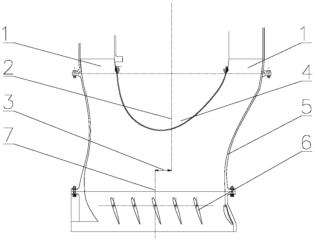
[0025] In order to make the purpose, technical solutions and advantages of the implementation of this application clearer, the technical solutions in the embodiments of the application will be described in more detail below in conjunction with the drawings in the embodiments of the application. In the drawings, the same or similar reference numerals indicate the same or similar elements or elements with the same or similar functions. The described embodiments are part of the embodiments of the present application, rather than all of the embodiments. The embodiments described below with reference to the accompanying drawings are exemplary, and are intended to explain the application, but should not be understood as a limitation to the application. Based on the embodiments in this application, all other embodiments obtained by those of ordinary skill in the art without creative work shall fall within the protection scope of this application. The embodiments of the present applic...


PUM


Abstract

The invention belongs to the field of structural designs of aircraft engines, and in particular relates to an asymmetrical exhaust structure of a lift fan. The asymmetrical exhaust structure comprisesan asymmetrical caudal vertebra (4), an adapting cartridge receiver (5) and a sprayer nozzle (6). A fairing adapting section is arranged on the adapting cartridge receiver (5), wherein one end of thefairing adapting section is connected to the asymmetrical caudal vertebra (4) and is coaxial with the lift fan; and the other end of the fairing adapting section is connected to the sprayer nozzle (6) and is coaxial with the sprayer nozzle (6). The middle part of the fairing adapting section is a smooth curved surface section. The lift fan is of an asymmetrical exhaust structure. The adapting cartridge receiver provided with the fairing adapting section is connected to the asymmetrical caudal vertebra and the sprayer nozzle, so that the exhaust loss of the lift fan can be reduced and the sprayer nozzle performance and the fan pneumatic performance are guaranteed.

Description

Technical field [0001] The application belongs to the field of aircraft engine structure design, and particularly relates to an asymmetric exhaust structure of a lift fan. Background technique [0002] The power lift fan for short take-off and vertical landing aircraft is a power system component that generates lift through a vertically downward nozzle. It provides a certain vectoring capability, so that the nozzle exhaust airflow direction can swing a certain angle forward and backward in the flight direction , To complete the specific action of the aircraft. The exhaust air of the lift fan flows into the nozzle from the outlet of the fan. The nozzle itself is difficult to move. A small size, light weight nozzle with vector adjustment capability is required, and the nozzle must have a stable flow from the fan outlet to the nozzle. The outlet should reduce the airflow loss to ensure the performance of the lift fan. [0003] The exhaust structure of the lift fan generally includes...

Claims


Application Information

Patent Timeline
IPC IPC(8): B64C11/00B64C29/04
CPCB64C11/001B64C29/04
Inventor 赵雷高兴李晓冲印雪梅丁拳
Owner AECC SHENYANG ENGINE RES INST
Learn More