Medium and low pressure gas-liquid separation device and method suitable for multiple working conditions

A technology of low-pressure gas-liquid separation and gas-liquid separator, which is applied in gas/liquid distribution and storage, earthwork drilling, mining fluid, etc. It can solve the problems that cannot meet the requirements of the production period, and achieve the effect of improving the recovery rate

Pending Publication Date: 2019-04-12
XIAN CHANGQING TECH ENG
View PDF0 Cites 3 Cited by
  • Summary
  • Abstract
  • Description
  • Claims
  • Application Information

AI Technical Summary

Problems solved by technology

Due to the different requirements for gas-liquid separation in different development periods, conventionally designed gas-liquid separation devices cannot meet the requirements of the above-mentioned production period

Method used


Image

  • Medium and low pressure gas-liquid separation device and method suitable for multiple working conditions

Examples


Embodiment 1

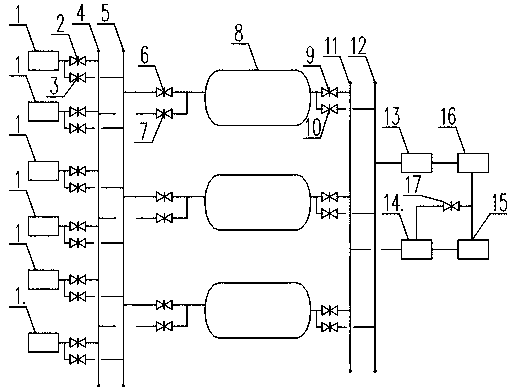
[0025] Due to the different requirements for gas-liquid separation in different development periods, conventionally designed gas-liquid separation devices cannot meet the requirements of the production period and the needs of downstream users. The present invention provides such figure 1 The shown is a medium-low pressure gas-liquid separation device and method suitable for multiple working conditions, which can meet the gas-liquid separation requirements of gas-gathering stations in different operation periods, and at the same time can realize low-pressure natural gas pressurized and exported to meet the needs of downstream users to improve the gas field. recovery rate.

[0026] A medium-low pressure gas-liquid separation device suitable for multiple working conditions, including a plurality of gas well inlet pipelines 1, a first low-pressure header 4 and a first medium-pressure header 5, a second low-pressure header 11, a second medium-pressure Manifold 12, compressor 15, ex...

Embodiment 2

[0032] Based on Embodiment 1, a third process switching valve 7 is provided between the first low-pressure manifold 4 and each gas-liquid separator 8 in this embodiment.

[0033] A fourth process switching valve 6 is arranged between the first medium pressure manifold 5 and each gas-liquid separator 8 .

[0034] A low-pressure flow meter 14 is provided between the second low-pressure manifold 11 and the compressor 15 .

[0035] A valve 17 is provided between the low-pressure flow meter 14 and the compressor 15 .

[0036] The valve 17 is a bypass valve.

[0037] A medium-pressure flowmeter 13 is arranged between the second medium-pressure manifold 12 and the outgoing pipeline 16 .

[0038] A fifth process switching valve 9 is provided between the second low-pressure manifold 11 and each gas-liquid separator 8 .

[0039] A sixth process switching valve 10 is provided between the second medium pressure manifold 12 and each gas-liquid separator 8 .

[0040] The gas well inlet ...

Embodiment 3

[0043] Based on the basis of Examples 1 and 2, a medium-low pressure gas-liquid separation method suitable for multiple working conditions is provided in this example, and the specific steps are:

[0044]Step 1. The gas well inlet pipeline 1 is switched to the header through the first process switching valve 2 and the second process switching valve 3 according to whether the inlet pressure is greater than the downstream external pressure. If it is greater than the downstream external pressure, the first process is closed. Switch valve 2, open the second process switching valve 3 to enter the first medium pressure manifold 5, otherwise close the second process switching valve 3, open the first process switching valve 2 to enter the first low pressure manifold 4;

[0045] Step 2. According to the total amount of low-pressure and medium-pressure gas entering the gas gathering station, the gas-liquid separator 8 is used as a medium-pressure separator or a low-pressure separator. As...


PUM


Abstract

The invention provides a medium and low pressure gas-liquid separation device and method suitable for multiple working conditions. The medium and low pressure gas-liquid separation device comprises aplurality of gas well inlet pipelines, a first low pressure manifold, a first medium pressure manifold, a second low pressure manifold, a second medium pressure manifold, a compressor, an external conveying pipeline and a plurality of gas-liquid separators arranged in parallel. The upstream of the parallel gas-liquid separators is connected with the first low pressure manifold and the first mediumpressure manifold, the downstream of the parallel gas-liquid separators is connected with the second low pressure manifold and the second medium pressure manifold correspondingly, the second low pressure manifold is connected with the external conveying pipeline through the compressor, and the downstream of the second medium pressure manifold is connected with the external conveying pipeline. First process switching valves and second process switching valves are separately arranged between each gas well inlet pipeline and the first low pressure manifold and the first medium pressure manifold.When the device runs under low pressure conditions, natural gas passing through the low pressure manifold is measured by a low pressure flowmeter and supercharged by the compressor, and then is transmitted to the external conveying pipeline to realize low pressure natural gas supercharging and external transportation, and the oil recovery of gas fields is improved.

Description

technical field [0001] The present invention relates to a multi-working-condition medium-low pressure gas-liquid separation device and method, in particular to a multi-working-condition medium-low pressure gas-liquid separation device that meets the gas-liquid separation requirements of gas-gathering stations in the process of natural gas exploitation in the oil and gas industry . Background technique [0002] In the development of natural gas fields, due to the different production capacity and production time of gas wells, the pressure and output entering the gas gathering station are also different. Boost mining to meet the needs of downstream users. Therefore, according to whether the pressure of the gas well entering the gas gathering station meets the needs of downstream users, the gas field is generally divided into the following three development periods: (1) In the early stage of development, the pressure of the gas well entering the gas gathering station is greate...

Claims


Application Information

Patent Timeline
IPC IPC(8): E21B43/34F17D1/04F17D3/01F17D3/14F17D3/18
CPCE21B43/34F17D1/04F17D3/01F17D3/145F17D3/18
Inventor 刘银春张颖王登海郑欣胡涛杜超康乐赵鹏敏李岩刘炳森蔡瑜史斌
Owner XIAN CHANGQING TECH ENG
Why Eureka
Try Eureka