A high pressure variable displacement plunger pump

A variable plunger and high pressure technology, applied in the field of high pressure variable plunger pumps, can solve the problems of large installed power, large floor space, and increased use costs, and achieve the effect of reducing displacement and realizing variable displacement

Active Publication Date: 2019-12-17
东营盛昶石油机械有限公司
View PDF8 Cites 0 Cited by
  • Summary
  • Abstract
  • Description
  • Claims
  • Application Information

AI Technical Summary

Problems solved by technology

[0002] The plunger pump is a hydraulic power component widely used in the hydraulic system. In most working conditions of the existing mechanical equipment, the plunger pump has the requirements of low pressure and large flow, high pressure and small flow. There are two solutions in the prior art. The first One is to use two plunger pumps, one large and one small, which are respectively driven by two motors, one large and one small. When the pressure of the hydraulic system reaches a certain pressure value, the large motor is turned off through the electronic control program so that the large pump is not working. , this kind of scheme needs to be equipped with two motors, which occupies a large area and has a large installed power, which increases the cost of use; the second scheme is to use double pumps and double pump confluence unloading valves, and the double pumps are driven by one motor , when the pressure of the hydraulic system reaches a certain pressure value, the double-pump confluence unloading valve is controlled by the electronic control program to unload the large-displacement pump outlet in the double-connected pump. Due to the high price of the double-connected pump, this kind of scheme The double-pump confluence unloading valve is large in size and high in cost, which also increases the cost of use
In addition, the above two solutions are only suitable for medium and low pressure hydraulic systems, that is, the pressure is lower than 35MPa. For hydraulic systems with system pressure greater than 35MPa, there is no good solution in the prior art

Method used


Image

  • A high pressure variable displacement plunger pump
  • A high pressure variable displacement plunger pump
  • A high pressure variable displacement plunger pump

Examples


Embodiment Construction

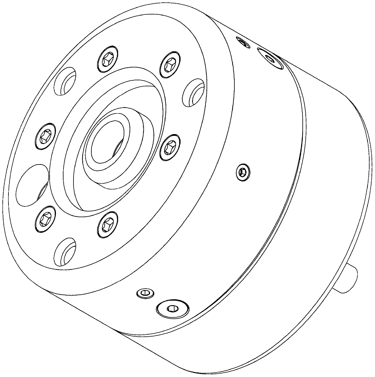
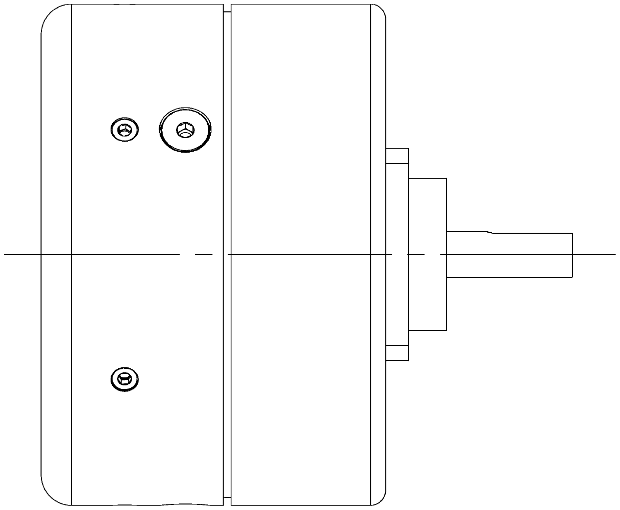
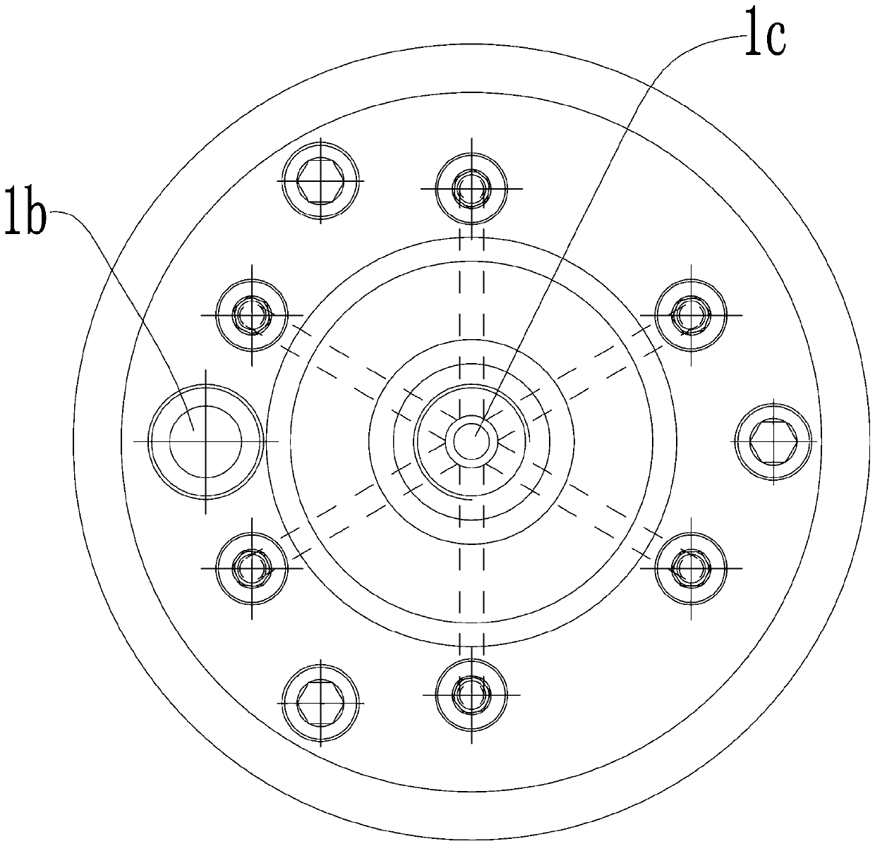
[0028] see Figure 1-10 As shown, a high-pressure variable displacement plunger pump includes a pump body 1 and a pump casing 19 installed on the right end surface of the pump body 1, an oil inlet chamber 1a is formed between the pump casing 19 and the right end surface of the pump body 1, The left end surface of the pump body 1 is provided with an oil inlet hole 1b communicating with the oil inlet chamber 1a; the right end surface of the pump body 1 is rotatably connected with a rotating shaft 17 protruding from the pump casing 19, and the oil inlet chamber 1a is internally On the right end surface of the pump body 1, six plunger modules are evenly installed with the rotating shaft 17 as the center. In the oil inlet chamber 1a, a shaft sleeve 21 is eccentrically installed on the shaft 17 through a pin key. On the shaft sleeve 21 A polygonal axle sleeve 22 with a regular hexagonal cross section is installed on it.

[0029] The plunger module includes a mounting block 13, a pl...


PUM


Abstract

The invention discloses a high-pressure variable plunger pump. The high-pressure variable plunger pump comprises a pump body and a pump shell arranged on the right end face of the pump body. An oil inlet cavity is formed between the pump shell and the right end face of the pump body, and an oil inlet hole is formed in the left end face of the pump body. The right end face of the pump body is rotationally connected with a rotation shaft, a plurality of plunger modules are arranged in the oil inlet cavity at equal intervals, the part, in the oil inlet cavity, of the rotation shaft is eccentrically provided with a shaft sleeve, and the shaft sleeve is provided with a multi-edge shaft sleeve. A second oil outlet hole is formed in the center position of the left end face of the pump body, a third oil outlet hole is formed in the pump body in the radial direction of the second oil outlet hole, and a plurality of fourth oil outlet holes are formed in the pump body. The communicating positionsof the third oil outlet hole and the fourth oil outlet holes in the pump body are provided with oil outlet one-way valve assemblies. The pump body is internally provided with a variable control valveassembly for controlling the flow of the second oil outlet hole. The high-pressure variable plunger pump is compact in size, low in cost and capable of being applied to the high pressure.

Description

technical field [0001] The invention relates to the technical field of plunger pumps, in particular to a high-pressure variable displacement plunger pump. Background technique [0002] The plunger pump is a hydraulic power component widely used in the hydraulic system. In most working conditions of the existing mechanical equipment, the plunger pump has the requirements of low pressure and large flow, high pressure and small flow. There are two solutions in the prior art. The first One is to use two plunger pumps, one large and one small, which are respectively driven by two motors, one large and one small. When the pressure of the hydraulic system reaches a certain pressure value, the large motor is turned off through the electronic control program so that the large pump is not working. , this kind of scheme needs to be equipped with two motors, which occupies a large area and has a large installed power, which increases the cost of use; the second scheme is to use double p...

Claims


Application Information

Patent Timeline
Patent Type & Authority Patents(China)
IPC IPC(8): F04B17/03F04B1/053F04B1/06
CPCF04B1/053F04B1/063F04B17/03
Inventor 刘斌
Owner 东营盛昶石油机械有限公司
Why Eureka
Try Eureka