Upper limb rehabilitation mechanical arm capable of changing shoulder center

A robotic arm and shoulder technology, which is applied in the field of shoulder center variable upper limb rehabilitation robotic arms, can solve the problems of high gas compressibility, short transmission distance, cumbersomeness, etc., and achieves good speed controllability, simple maintenance, and transmission. smooth effect

Pending Publication Date: 2019-06-14
ANHUI UNIV OF SCI & TECH
View PDF0 Cites 0 Cited by
  • Summary
  • Abstract
  • Description
  • Claims
  • Application Information

AI Technical Summary

Problems solved by technology

[0006] The research on exoskeleton rehabilitation robots is relatively extensive. According to the joint control type, it can be divided into serial type and parallel type. According to the driving type, it can be divided into artificial pneumatic drive and motor direct drive. The disadvantage of artificial pneumatic type is that when inflated, due to Gas is highly compressible and difficult to precisely control
Motor direct drive products use the motor to be directly installed on the joints to be driven. The advantage is that the power generated by the motor directly acts on each joint, the transmission distance is short, and the transmission loss is small, which can realize precise control of each joint. The disadvantage is that It takes up a lot of space, and the installation of the servo motor needs to add parts such as reducers, etc., and the parts of the whole device will be cumbersome
[0007] At present, some main problems of exoskeleton rehabilitation robots are as follows: 1. At present, the main exoskeleton upper limb rehabilitation equipment rarely has a mechanism with a variable shoulder center, which cannot fully meet the rehabilitation requirements of patients with shoulder injuries
2. Long-term mechanical pulling of the joints will cause secondary damage to the patient, and the clinical manifestation is pain in the limbs after rehabilitation training

Method used


Image

  • Upper limb rehabilitation mechanical arm capable of changing shoulder center
  • Upper limb rehabilitation mechanical arm capable of changing shoulder center
  • Upper limb rehabilitation mechanical arm capable of changing shoulder center

Examples


Embodiment Construction

[0031] In order to make the technical means, creative features, objectives and effects achieved by the present invention easy to understand, the present invention will be further described below in conjunction with specific embodiments and illustrations.

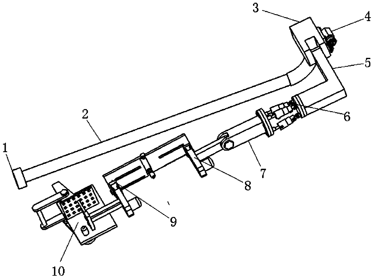
[0032] like figure 1 As shown, a shoulder center variable upper limb rehabilitation robotic arm includes a base 1, a support frame 2, a shoulder joint 3, a shoulder motor 4, a shoulder connecting rod 5, a 3-DOF parallel hydraulic platform 6, and a large arm connecting rod 7. Big arm 8, elbow joint 9, wrist joint 10. The base 1 and the support frame 2 are connected by bolts. The lower end of the support frame 2 is connected with the base 1 by bolts, and the upper end is bent at 90 degrees and connected with the shoulder joint 3 by bolts.

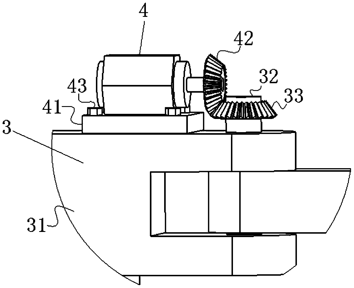
[0033] like figure 2As shown, the shoulder joint includes a beam 31 and a rotation shaft 32 . Wherein, the beam 31 is connected with the support frame 2; the rotating shaft 32 is equip...


PUM


Abstract

The invention discloses an upper limb rehabilitation mechanical arm capable of changing the shoulder center. The upper limb rehabilitation mechanical arm comprises a base, a supporting frame, a shoulder joint, a shoulder motor, a shoulder connecting rod, a 3-DOF parallel hydraulic platform, a big arm connecting rod, a big arm, an elbow joint and a wrist joint, and the shoulder joint comprises a transverse beam and a rotary shaft; the shoulder motor comprises a motor, a fixed base and a bevel gear; the 3-DOF parallel hydraulic platform comprises an upper bottom plate, three telescopic hydrauliccylinders and a lower bottom plate; the big arm comprises a holder, a driving motor, an upper connecting plate and a rotating shaft; the elbow joint comprises a small driving motor, a big driving motor, a small holder, a large holder and a lower connecting plate; the wrist joint comprises a driving motor, a holder, a wrist baffle, a belt pulley, a wrist connecting rod, a bolt connecting rod and abolt. According to the upper limb rehabilitation mechanical arm, the shoulder center can be changed so that the shoulder joint can move in any direction no matter where the big arm and the forearm ofthe arm are, and the upper limb rehabilitation mechanical arm has the advantages of being compact in structure, high in practicability and the like.

Description

technical field [0001] The invention relates to the field of medical technology, in particular to a shoulder center variable upper limb rehabilitation mechanical arm. Background technique [0002] According to the World Health Research Report, cardiovascular disease is currently one of the five major chronic diseases affecting the daily life of all human beings. The high incidence of such diseases is the elderly population. my country is an area with a high incidence of stroke patients. There are about 8 million stroke patients. At the same time, studies have shown that 75% of patients have sequelae and disabilities of varying degrees, which greatly hinders patients. Normal daily activities also increase the burden on the family and affect the quality of life of the family. At the same time, my country has entered an aging society since 2000. According to the census data, the population aged 60 and above accounted for 13.26%, of which the population aged 65 and above account...

Claims


Application Information

Patent Timeline
Patent Type & Authority Applications(China)
IPC IPC(8): A61H1/02B25J9/00
Inventor 李宪华刘壮壮吕磊费思先石雪松孙青盛蕊
Owner ANHUI UNIV OF SCI & TECH
Why Eureka
Try Eureka