Bi-directional rotating spherical pump cooling mechanism

A cooling mechanism and two-way rotation technology, applied in the field of hydraulic pumps, can solve the problems of inability to achieve cooling and friction pair cooling, and achieve the effects of good production and processing technology, low processing cost and high cooling efficiency

Pending Publication Date: 2019-04-12
深圳市球形动力科技有限公司
View PDF10 Cites 1 Cited by
  • Summary
  • Abstract
  • Description
  • Claims
  • Application Information

AI Technical Summary

Problems solved by technology

[0002] The spherical pump is a variable capacity mechanism with a new structure newly invented in recent years. During the operation of the spherical pump, since the main moving parts such as the piston, turntable, and central shaft are in the flowing liquid, the heat generated during the operation Taken away by the continuously flowing liquid, the temperature of the friction pair of the piston, the turntable and the central shaft does not rise much, and no special cooling is required; The accumulation of liquid leaking from the spherical inner cavity cannot effectively cool the corresponding friction pair, resulting in excessive temperature of the main shaft sleeve, bearing, and upper moving part of the main shaft as the rotating radial friction pair of the main shaft. The patent number is CN201610266963.5, and the patent name The Chinese patent titled "Spherical Pump Cooling Mechanism" with patent number CN201610594749.2 and patent name "A Spherical Pump with Interstitial Cooling Function" proposed a corresponding technical solution for the cooling of the above-mentioned spherical pump, and achieved certain results. Technical effect, but the former can only achieve cooling for the spherical pump with one-way rotation, and cannot achieve cooling when the spherical pump is reversed; the biggest disadvantage of the latter is that the volumetric efficiency of the pump is sacrificed while achieving cooling

Method used


Image

  • Bi-directional rotating spherical pump cooling mechanism
  • Bi-directional rotating spherical pump cooling mechanism
  • Bi-directional rotating spherical pump cooling mechanism

Examples


Embodiment Construction

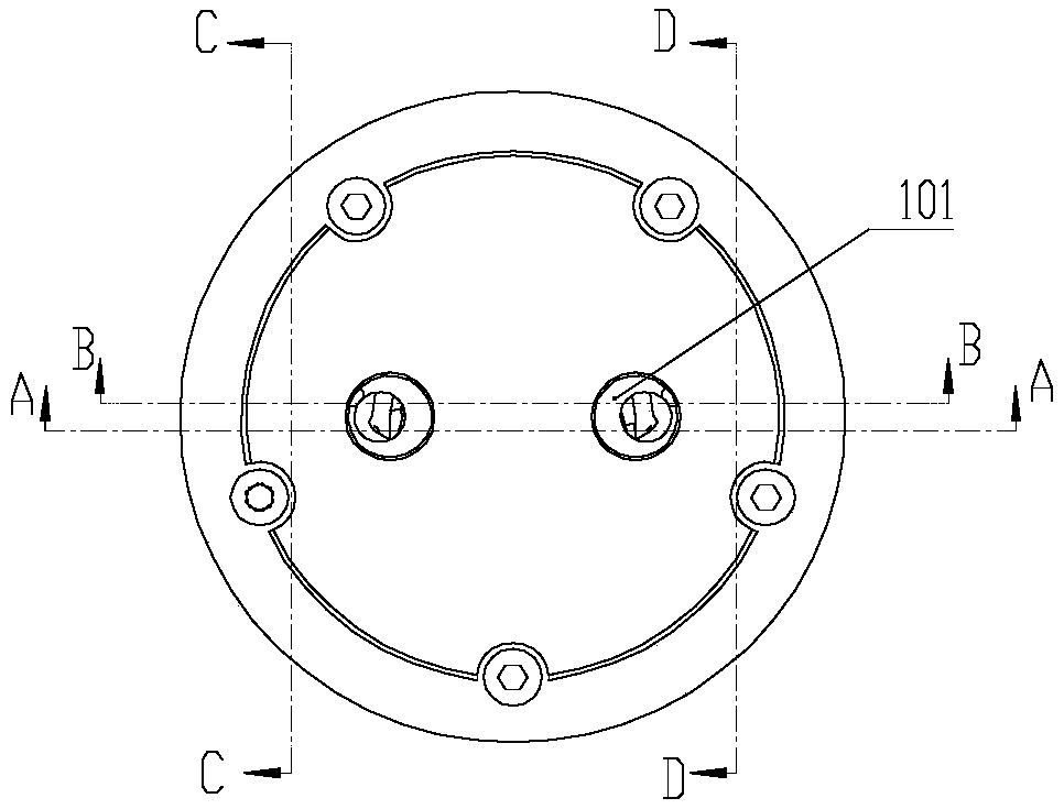
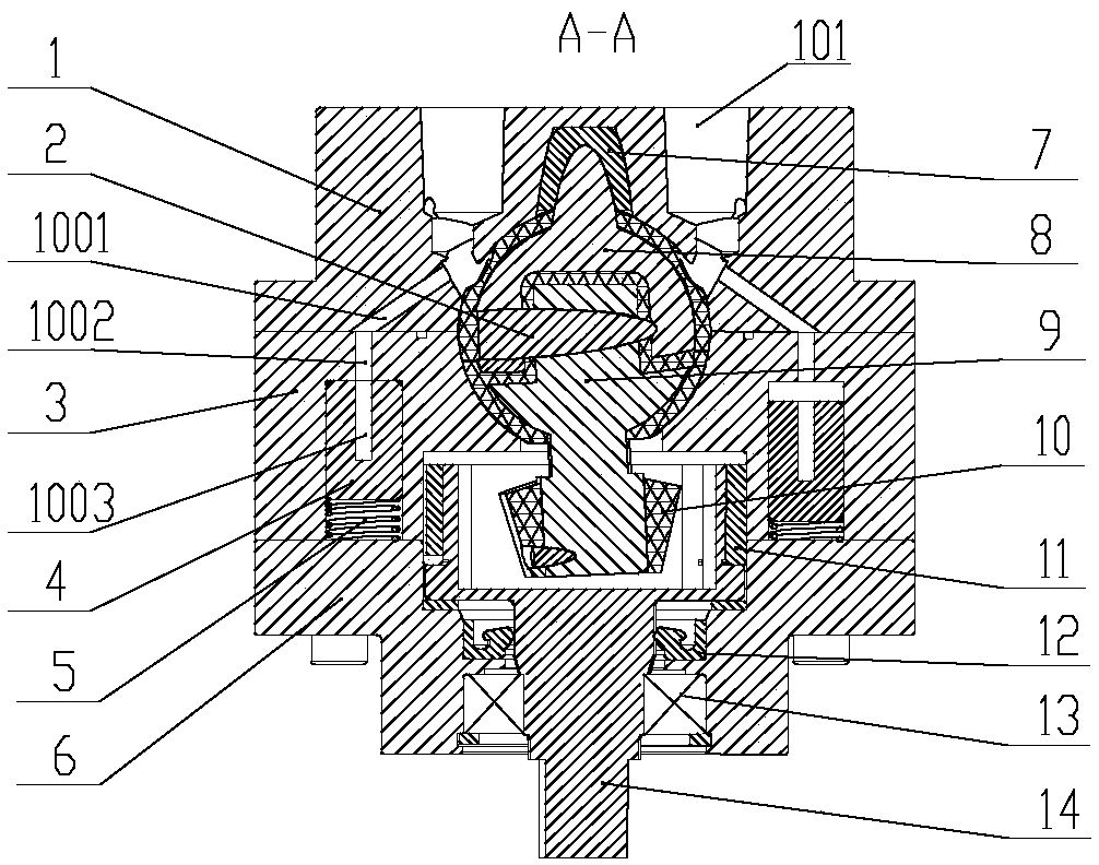
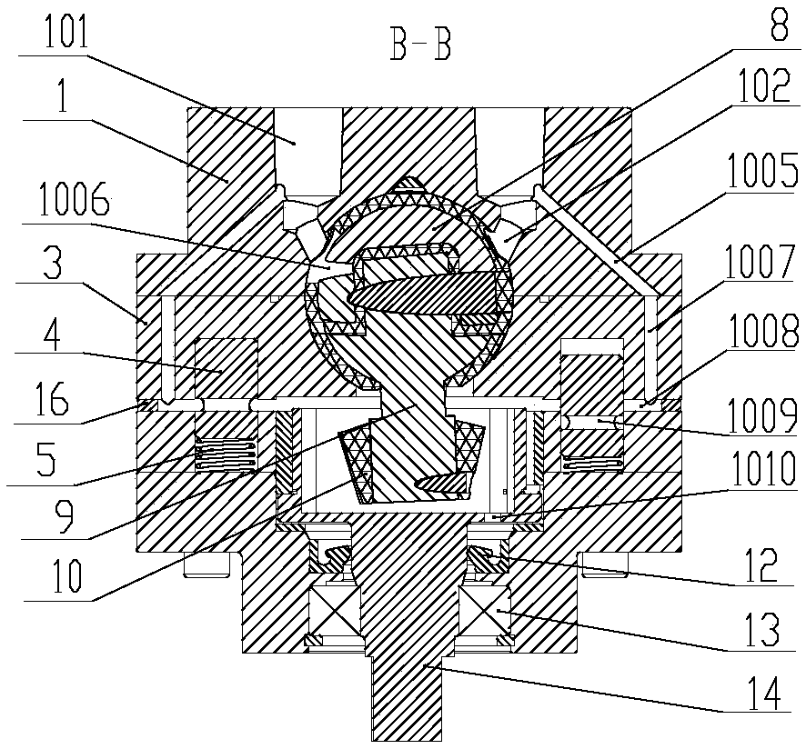
[0037] like Figure 1 to Figure 3 , Figure 6 to Figure 9 As shown, the structure of the spherical compressor is the same as that of a conventional spherical compressor. The spherical pump includes a cylinder head 1, a cylinder body 3, a piston 8, a turntable 9, a central shaft 2, a main shaft 14, a main shaft support 6, etc.; Cylinder head screw holes 103 and two positioning pin holes 104, five corresponding cylinder body threaded holes 106 and two positioning pin holes 104 are arranged on the cylinder body 3, the cylinder head 1 and the cylinder body 3 have a hemispherical inner spherical surface, The cylinder head 1 and the cylinder body 3 are connected by screws to form a spherical inner cavity, and a through hole adapted to the working process of the turntable shaft is provided in the center of the lower inner spherical surface of the cylinder body 3, and a spindle sleeve is also provided on the lower end surface of the cylinder body 3. 11. The main shaft sleeve hole 109...


PUM


Abstract

The invention discloses a bi-directional rotating spherical pump cooling mechanism. An inlet / discharging hole (101), a cylinder cover flow dividing channel (1005), a cylinder body flow dividing channel (1007) and a cylinder body flow guiding channel (1008) sequentially communicate with one another to form a flow dividing part of each cooling channel. A main shaft support flow guiding groove (1004), a cylinder body lower end flow returning channel (1011), a cylinder body upper end flow returning channel (1002), a cylinder cover flow returning channel (1001) and an inlet / discharging hole (101) sequentially communicate with one another to form a flow returning part of each cooling channel. A cylinder body is provided with switching valves. Each switching valve controls the on state of the corresponding cylinder body flow guiding channels (1008) and controls the corresponding cylinder body lower end flow returning channel (1011) to communicate with the corresponding cylinder body upper endflow returning channel (1002). The bi-directional rotating spherical pump cooling mechanism can be applied to cooling and lubricating under the circumstance that a spherical pump rotates forwards andbackwards; and meanwhile, the volume efficiency of the spherical pump is not lowered.

Description

technical field [0001] The patent of the present invention relates to the technical field of hydraulic pumps, in particular to a bidirectional rotary spherical pump cooling mechanism. Background technique [0002] The spherical pump is a variable capacity mechanism with a new structure newly invented in recent years. During the operation of the spherical pump, since the main moving parts such as the piston, turntable, and central shaft are in the flowing liquid, the heat generated during the operation Taken away by the continuously flowing liquid, the temperature of the friction pair of the piston, the turntable and the central shaft does not rise much, and no special cooling is required; The accumulation of liquid leaking from the spherical inner cavity cannot effectively cool the corresponding friction pair, resulting in excessive temperature of the main shaft sleeve, bearing, and upper moving part of the main shaft as the rotating radial friction pair of the main shaft. T...

Claims


Application Information

Patent Timeline
Patent Type & Authority Applications(China)
IPC IPC(8): F04C9/00F04C15/00F16K3/26
CPCF04C9/00F04C15/00F04C15/0096F16K3/262F04C2240/20F04C2240/30F05C2251/14F05C2225/12F05C2201/0448
Inventor 张五星邹姜昆谈耀文王陆一
Owner 深圳市球形动力科技有限公司
Why Eureka
Try Eureka