Method and system for identifying on-orbit vibration state of satellite flexible accessories using gyroscope data

A technology of data and accessories, applied in vibration testing, testing of machine/structural components, measuring devices, etc., can solve problems such as difficult known excitation of in-orbit spacecraft, increased design difficulty, and increased number of drive mechanism slip ring signal channels, etc.

Active Publication Date: 2020-08-25
SHANGHAI SATELLITE ENG INST
View PDF10 Cites 0 Cited by
  • Summary
  • Abstract
  • Description
  • Claims
  • Application Information

AI Technical Summary

Problems solved by technology

[0004] The above identification methods of dynamic parameters of flexible satellites in orbit have two constraints in terms of engineering application: one is that it is difficult to apply known excitations required for dynamic parameter identification on orbiting spacecraft, and only the deployment and retraction of the space structure in orbit can be used. , The docking and separation of the structure, the ignition of the engine, etc. generate excitation sources for excitation, and the signals of these excitation sources are difficult to measure [Research on Identification Technology of Dynamic Parameters of On-orbit Spacecraft——Yu Dengyun]
Second, the number of vibration sensors installed on flexible accessories is limited by engineering implementation
Generally, flexible accessories need to be deployed on rails, and the installation and fixing of various speed, acceleration, and displacement sensors, as well as cable laying, will have adverse effects on the deployment mechanism, increasing the difficulty of design
In addition, for rotating flexible components such as solar arrays, it is necessary to increase the number of signal channels of the drive mechanism slip ring

Method used


Image

  • Method and system for identifying on-orbit vibration state of satellite flexible accessories using gyroscope data
  • Method and system for identifying on-orbit vibration state of satellite flexible accessories using gyroscope data
  • Method and system for identifying on-orbit vibration state of satellite flexible accessories using gyroscope data

Examples


Embodiment approach

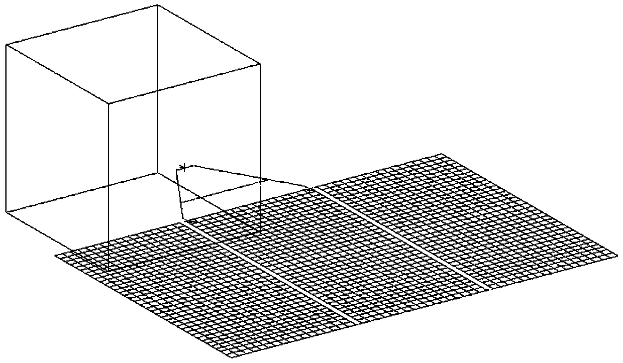
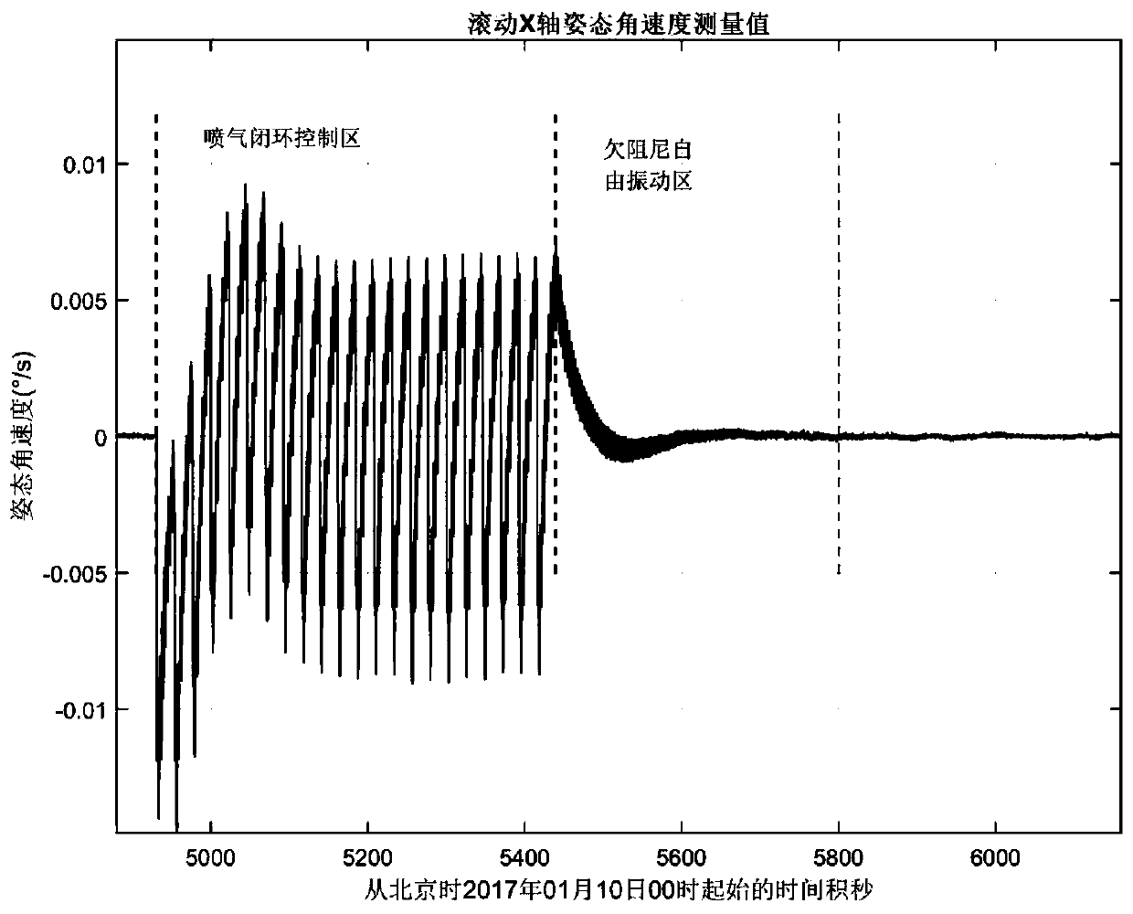
[0079] A remote sensing satellite is equipped with a single-wing solar cell array, the configuration is shown in figure 1 . After launching into orbit, the rolling X-axis attitude angular velocity measurement data during jet control is as follows: figure 2 shown.

[0080] Step 1: Select the rolling X-axis attitude angular velocity measurement data ω during the satellite’s in-orbit operation X (t) to analyze ( figure 2 ).

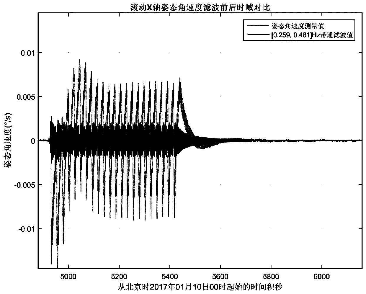
[0081] Step 2: According to the calculation results of the structural dynamics analysis of the whole satellite on the ground, the frequency of the main vibration mode in the X direction is about 0.37Hz, set the vibration frequency band of interest to [0.259,0.481]Hz, and use the 5th-order Butterworth bandpass filter The attitude angular velocity measurement data ω of the satellite in-orbit operation X (t) Perform filter processing to strip the long-period motion and high-frequency vibration components in the rolling X-axis attitude angular velocity si...


PUM


Abstract

The invention provides a method for identifying the in-orbit vibration state of flexible satellite accessories by gyro data. The method comprises the following steps that the attitude angular velocityis obtained, specifically, attitude angular velocity measurement data corresponding to an i axis of an under-damped free vibration region after satellite in-orbit air-jet closed-loop control is obtained; filtering is conducted, specifically, omega (t) is subjected to filtering to obtain the filtered attitude angular velocity data omega' (t) of the i axis; time series calculation is conducted, specifically, according to the omega' (t), time series eta (t) of a modal variable is obtained through calculation; overall displacement is obtained; end displacement is calculated; and relative displacement is calculated. The invention further provides a system for identifying the in-orbit vibration state of the flexible satellite accessories by the gyro data correspondingly. Other sensors do not need to be mounted on the flexible accessories, and analysis processing is conducted only by measurement data of existing attitude sensors on a satellite platform.

Description

technical field [0001] The invention relates to the field of satellite monitoring, in particular to a method and system for identifying the on-orbit vibration state of a satellite flexible accessory by using gyroscope data. In particular, it relates to an on-orbit identification method and system for vibration state information of a flexible satellite, specifically a method and system for identification of overall displacement, end displacement and relative displacement during on-orbit vibration of a flexible satellite. Background technique [0002] With the continuous development of aerospace technology, large-scale space structures have become an important development direction in the field of aerospace, and will also be the necessary infrastructure for space development [Research on Identification Technology of Dynamic Parameters of In-orbit Spacecraft—Yu Dengyun]. In order to obtain the dynamic characteristics of flexible satellite structures, finite element modeling, gr...

Claims


Application Information

Patent Timeline
Patent Type & Authority Patents(China)
IPC IPC(8): G01M7/02
CPCG01M7/02G01M7/025
Inventor 吕旺董瑶海邓泓刘培玲宋效正曾擎
Owner SHANGHAI SATELLITE ENG INST
Why Eureka
Try Eureka