
Pluggable modular box with expansibility

A scalable, box-like technology, applied in the field of urban public equipment, can solve problems such as the inability to realize plug-and-play functional modules, no corresponding disclosure, modular box volume water, etc., to achieve convenient power supply, communication, and design Ingenious, easy to integrate and install the effect

Inactive Publication Date: 2019-04-12
重庆光电信息研究院有限公司
View PDF7 Cites 3 Cited by
  • Summary
  • Abstract
  • Description
  • Claims
  • Application Information

AI Technical Summary

Problems solved by technology

[0003] 1. The modularized box involves many electrical components. The electrical components are installed in the electrical cavity. When the surrounding air is affected by temperature changes, it is easy to form condensed water in the cavity when the temperature drops. If the condensed water is not discharged in time, it is easy to cause the module The volume of water in the tank, and because the electrical components are heating elements, if the heat is not dissipated in time, the temperature of the electrical components will be too high, resulting in damage to the electrical components
[0004] 2. When installing electrical components in the modular box, most of them are installed in the electrical cavity at random, and there is no installation plane, which is inconvenient to install; at the same time, there is no isolation between the screw hole of the modular box and the electrical cavity design, not waterproof
[0005] 3. There are many parts installed in the modular box in the prior art, resulting in a heavy load on the modular box, but the modular box in the prior art has no design to reduce the load; the modular box in the prior art is due to the structure Restrictions lead to relatively high cost in the production and manufacture of modular cabinets in the prior art
[0006] 4. There are many functional components involved in the smart light, and each functional component needs to be connected by an interface. However, the distribution of interfaces on the main body of the box on the existing smart light is not uniform, and the power supply and communication components need to be installed separately. The wiring is complicated, which can easily lead to pipeline accidents, and the plug-and-play of functional modules cannot be realized
However, there is no corresponding technical solution for preventing accumulation of water while dissipating heat, providing an installation plane for electrical components, reducing load, facilitating installation of different functional components, facilitating power supply and communication, and realizing plug-and-play of energy modules. public
[0008] To sum up, there is a need for a method that can prevent water accumulation and dissipate heat at the same time, provide an installation plane for electrical components, reduce load, facilitate the installation of different functional components, facilitate power supply and communication, and realize plug-and-play scalability of energy modules. Modular box, and there is no report about this modular box

Method used


Image

  • Pluggable modular box with expansibility
  • Pluggable modular box with expansibility
  • Pluggable modular box with expansibility

Examples


Embodiment 1

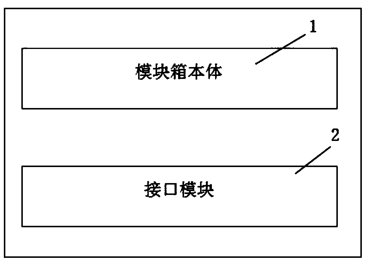
[0065] Please refer to figure 1 , figure 1 It is a structural schematic diagram of an expandable pluggable modular box invented by the invention. A pluggable modular box with expandability, the modular box includes a module box body 1 and an interface module 2.

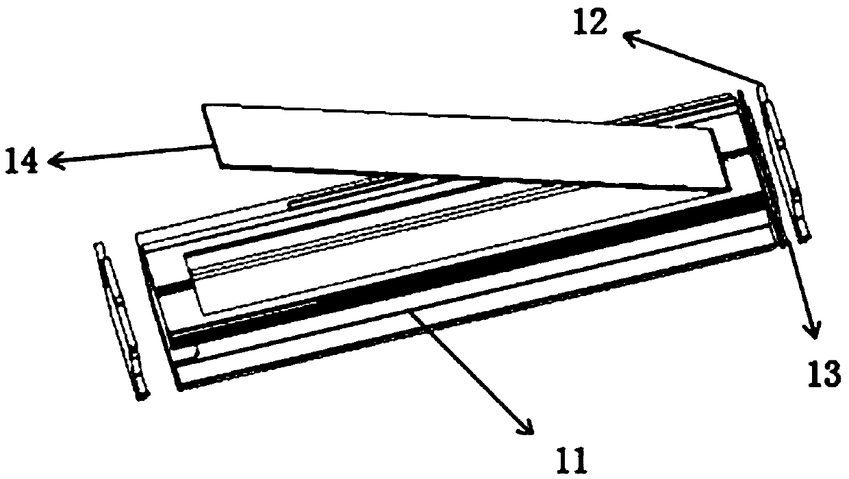
[0066] Please refer to figure 2 , figure 2 It is a schematic diagram of the structure of the modular box. Described module case body 1 comprises box body main body 11; Box body main body 11 both sides are equipped with sealing plate 12 by bolt, and the outer side of described sealing plate 12 is equipped with waterproof gasket 13; Plate 14 forms an electrical cavity 15 inside, and the flap 14 is hinged with the box body 11; the flap 14 is integrally formed with the box body 11 and then cut; the inner wall of the electrical cavity 15 is surrounded by guides. The water groove 3; the size specification of the water guiding groove 3 is 3mm-10mm.

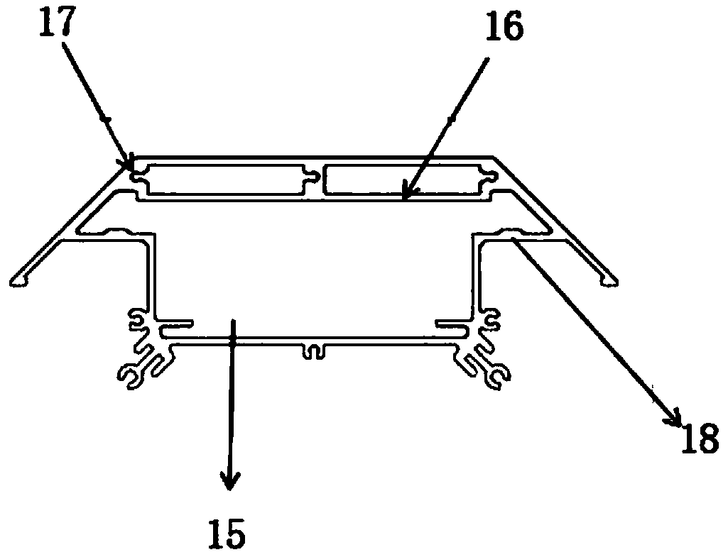
[0067] Please refer to image 3 , image 3 is a cross-sectional s...

Embodiment 2

[0082] Please refer to Figure 10 , Figure 10 It is a schematic diagram that the interface module 2 is arranged in the middle of the box main body 11 . This embodiment is basically the same as Embodiment 1, the difference is that the interface module 2 in this embodiment is arranged in the middle of the box main body 11 . When the interface module 2 is arranged in the middle of the box body 11, grooves 3 are provided on both sides of the box body 11; waterproof joints 4 are installed in the grooves 3, and the waterproof joints 4 adopt a distribution form of four in and four out; The waterproof joint 4 can also be stretched to the lower sealing plate 12 of the box main body 11 to connect the power line and the communication line.

[0083] Please refer to Figure 11 and Figure 12 , Figure 11 It is a schematic diagram of wiring of multiple box main bodies 11 . Figure 12 It is a schematic diagram of the top view direction of Fig. 11. When there are multiple box main bod...

Embodiment 3

[0085] Please refer to Figure 13 , Figure 13 It is a design schematic diagram of the interface module 2 of Embodiment 3. This embodiment is basically the same as Embodiment 1, except that the interface module 2 of this embodiment is provided with the bottom end of the box body 11, that is, a cavity is dug at the lower end of the box body 11 to form an electrical wiring cavity, and combined with The sealing plate 12 hides the wires, so that the bottom of the electrical wiring cavity forms a cavity with accommodating space, which facilitates the routing and placement of the box body 11 to hide redundant wires, and improves the safety and aesthetics of the box body 11; Water resistance and ease of operation.

[0086]The expandable pluggable modular box of the present invention can prevent accumulated water and dissipate heat at the same time, provide an installation plane for electrical components, reduce load, facilitate the installation of different functional components, f...


PUM


Abstract

The invention relates to a pluggable modular box with expansibility. The modular box comprises a box main body and an interface module; sealing plates are arranged on the two sides of the box main body through bolts; waterproof gaskets are arranged on the outer sides of the sealing plates; a turnover plate is cut and formed in the middle of the inner side of the box main body, an electric cavity is formed inside the box main body, and the turnover plate is hinged to the box main body; and a water guiding groove is formed in the periphery of the inner wall of the electric cavity. The pluggablemodular box with expansibility has the advantages that accumulated water can be prevented while heat dissipation can be performed synchronously; a mounting plane is provided for electrical elements, loads can be reduced, the installation of different functional components can be facilitated, power supply and communication are facilitated, plug and play of an energy module can be realized, and installation and maintenance of the box body are facilitated.

Description

technical field [0001] The invention relates to the technical field of urban public equipment, in particular to a modular box. Background technique [0002] Nowadays, China is vigorously carrying out the construction of smart cities. As an excellent carrier in the construction of smart cities, smart street lights need to be given more public service functions to street lights. At present, street lamp renovation usually adopts the method of removing the original street lamp and replacing it with smart street lamp. However, there are the following defects and deficiencies in the modular cabinets used in the prior art smart lights: [0003] 1. The modularized box involves many electrical components. The electrical components are installed in the electrical cavity. When the surrounding air is affected by temperature changes, it is easy to form condensed water in the cavity when the temperature drops. If the condensed water is not discharged in time, it is easy to cause the modu...

Claims


Application Information

Patent Timeline
Patent Type & Authority Applications(China)
IPC IPC(8): H05K5/06H05K7/02H05K7/14H05K5/02
CPCH05K5/0217H05K5/0247H05K5/069H05K7/02H05K7/14
Inventor 黄敏吴刚邓小波王志超张艳熊路舒莉李祥兰黄郁薇
Owner 重庆光电信息研究院有限公司
Learn More