Method for monitoring heart rate and heart rate variability and nursing type monitoring device

A heart rate variability and heart rate technology, used in telemetry patient monitoring, diagnostic recording/measurement, medical science, etc., to solve problems such as the inability to achieve continuous long-term monitoring

Inactive Publication Date: 2019-04-16
BEIGU NEW MATERIAL TECH SHANGHAI
View PDF11 Cites 3 Cited by
  • Summary
  • Abstract
  • Description
  • Claims
  • Application Information

AI Technical Summary

Problems solved by technology

The heart sound auscultation equipment is an electronic stethoscope, which needs to be attached to the human body for me

Method used


Image

  • Method for monitoring heart rate and heart rate variability and nursing type monitoring device
  • Method for monitoring heart rate and heart rate variability and nursing type monitoring device
  • Method for monitoring heart rate and heart rate variability and nursing type monitoring device

Examples


Embodiment 1

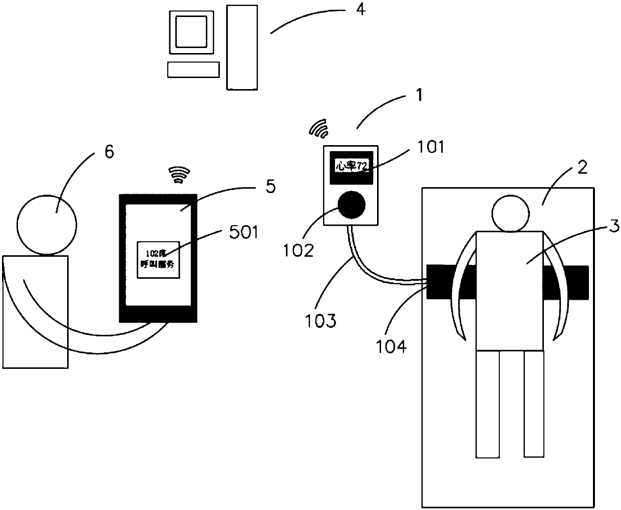
[0046] figure 1 It is a structural schematic diagram of the nursing monitoring device of the first embodiment.

[0047] Such as figure 1As shown, the nursing monitoring device includes: a monitoring terminal 1 , a cloud server 4 and an alarm device terminal 5 . The monitoring terminal 1 includes: a real-time display screen 101 , a call button 102 , a wire 103 and a sensor 104 . The monitoring terminal 1 is connected to the sensor 104 through a wire 103 , and a real-time display screen 101 and a call button 102 are set on the monitoring terminal 1 . The alarm device 5 can directly adopt a smart phone, and no additional configuration is required.

[0048] In this embodiment, the sensor 104 is placed above the mattress 2 and below the chest cavity of the care receiver 3 . When the care receiver 3 triggers the call button 102 , the monitoring terminal 1 transmits a signal to the cloud server 4 , and the cloud server 4 controls the alarm device 5 to send an alarm message 501 af...

Embodiment 2

[0058] In this embodiment, except that the structure of the sensor is different from that of Embodiment 1, the structures and working principles of other components are the same, and will not be described again.

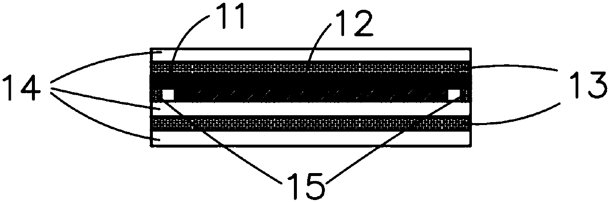
[0059] Such as Figure 8 As shown, the sensor in this embodiment includes: a sensitive layer 21 , a signal electrode layer 22 and an insulating layer 24 arranged in sequence. The sensor also includes a ground electrode layer 23, and the ground electrode layer 23 has a rectangular frame structure. The sensitive layer 21 , the signal electrode layer 22 and the insulating layer 24 are wrapped in the ground electrode layer 23 ; a layer of insulating layer 24 is arranged above and below the ground electrode layer 23 .

Embodiment 3

[0061] In this embodiment, except that the structure of the sensor is different from that of Embodiment 1, the structures and working principles of other components are the same, and will not be described again.

[0062] Such as Figure 9 As shown, the sensor in this embodiment includes: an insulating layer 34 , a negative signal electrode layer 35 , a sensitive layer 31 , a positive signal electrode layer 32 and an insulating layer 34 arranged in sequence. The sensor also includes a ground electrode layer 33, the ground electrode layer 33 is a rectangular frame structure; the insulating layer 34, the negative signal electrode layer 35, the sensitive layer 31, the positive signal electrode layer 32 and the insulating layer 34 are wrapped in the ground electrode layer 35; An insulating layer 34 is provided above and below the ground electrode layer 33 .


PUM


Abstract

The invention provides a method for monitoring the heart rate and the heart rate variability. The method includes the following steps of obtaining heartbeat signals with the frequency range of 10-80 Hz through a sensor, calculating the power of the obtained heartbeat signals, conducting at least one time of filtering on the power-calculated signals, and conducting peak point recognition on the filtered signals, wherein the peak points are heartbeat moment points. The method has the advantages that the human body heartbeat signals are extracted through the sensor, heart sound frequency band signals of the heartbeat signals are extracted, the more accurate and reliable heartbeat moment points are obtained, and therefore the heart rate and the heart rate variability are calculated.

Description

technical field [0001] The invention relates to a nursing monitoring device for monitoring heart rate and heart rate variability. Background technique [0002] Heart rate and heart rate variability are key indicators for assessing human health. The heart rate variability analysis can help evaluate the human sleep and stress status. However, medical methods and devices for detecting heart rate and heart rate variability based on electrocardiogram (ECG) and photoplethysmography (PPG) all need to be worn by the human body and are relatively cumbersome to use. [0003] A more convenient and wear-free method for monitoring heart rate and heart rate variability based on ballistocardiography (BCG) was proposed and developed. Detects the mechanical shock force signal generated by the heartbeat in the ballistocardiogram (BCG). When the posture of the human body changes, the main peak signal of the heartbeat impact force signal in BCG changes or even weakens. The algorithm using pe...

Claims


Application Information

Patent Timeline
IPC IPC(8): A61B5/0205A61B5/11A61B5/00
CPCA61B5/0004A61B5/0205A61B5/02405A61B5/0826A61B5/1118A61B5/4818A61B5/6891A61B5/6892A61B5/7203A61B5/725A61B5/746A61B5/747
Inventor 李彦坤吴涛
Owner BEIGU NEW MATERIAL TECH SHANGHAI
Why Eureka
Try Eureka