Semi-automatic electromagnetic riveting device of conical-tubular-structure workpiece

A semi-automatic and electromagnetic riveting technology, which is applied in the field of electromagnetic riveting devices, can solve the problems of difficult riveting and poor practicability of workpieces with conical cylindrical structures, and achieves the effects of good practicability, convenient adjustment, quick clamping and fastening

Active Publication Date: 2019-04-16
SHAANXI DAGONG XUHANG ELECTROMAGNETIC TECH CO LTD
View PDF6 Cites 0 Cited by
  • Summary
  • Abstract
  • Description
  • Claims
  • Application Information

AI Technical Summary

Problems solved by technology

[0003] In order to overcome the shortcomings of poor practicability of existing electromagnetic riveting devices, the present invention provides a semi-automatic electromagnetic riveting device for conical cylindrical structural parts
The fixed support frame and support column assembly make the fixed box horizontal and stable; the positioner assembly realizes the displacement, flip and rotation of the workpiece, and facilitates the adjustment of the riveting position of the workpiece; the riveting executive assembly makes the electromagnetic riveter and the top iron move up and down, which is convenient The riveting gun enters the workpiece, which solves the technical problem of difficult riveting of conical cylindrical structure workpieces

Method used


Image

  • Semi-automatic electromagnetic riveting device of conical-tubular-structure workpiece
  • Semi-automatic electromagnetic riveting device of conical-tubular-structure workpiece
  • Semi-automatic electromagnetic riveting device of conical-tubular-structure workpiece

Examples


Embodiment Construction

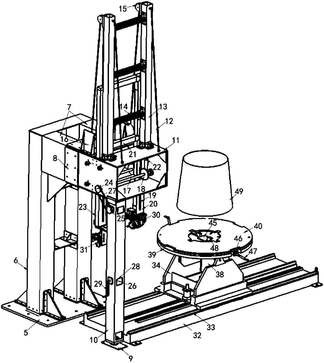
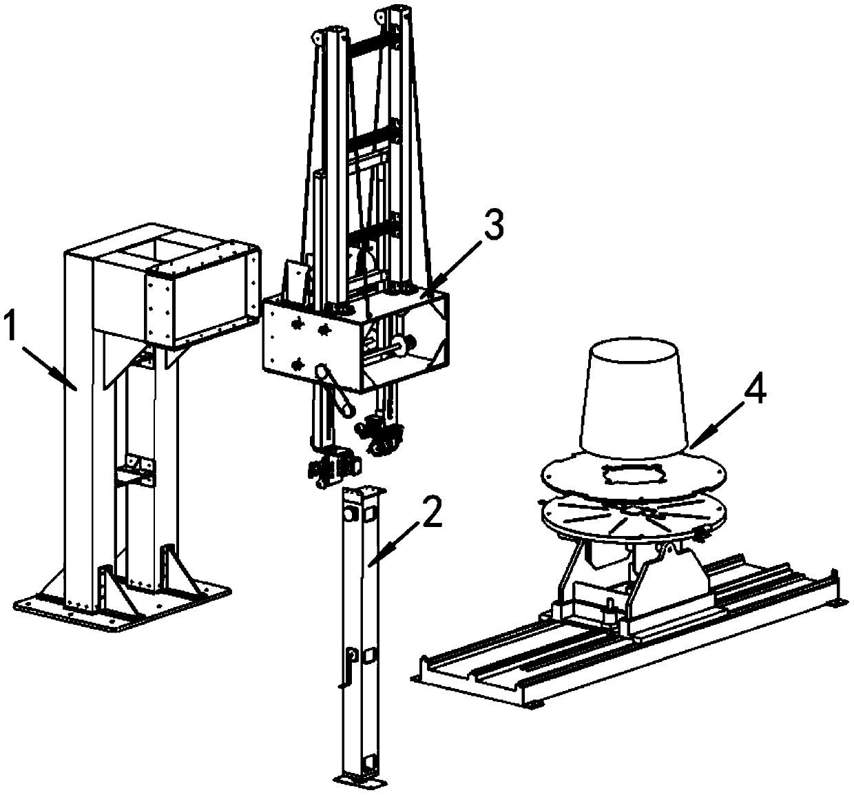
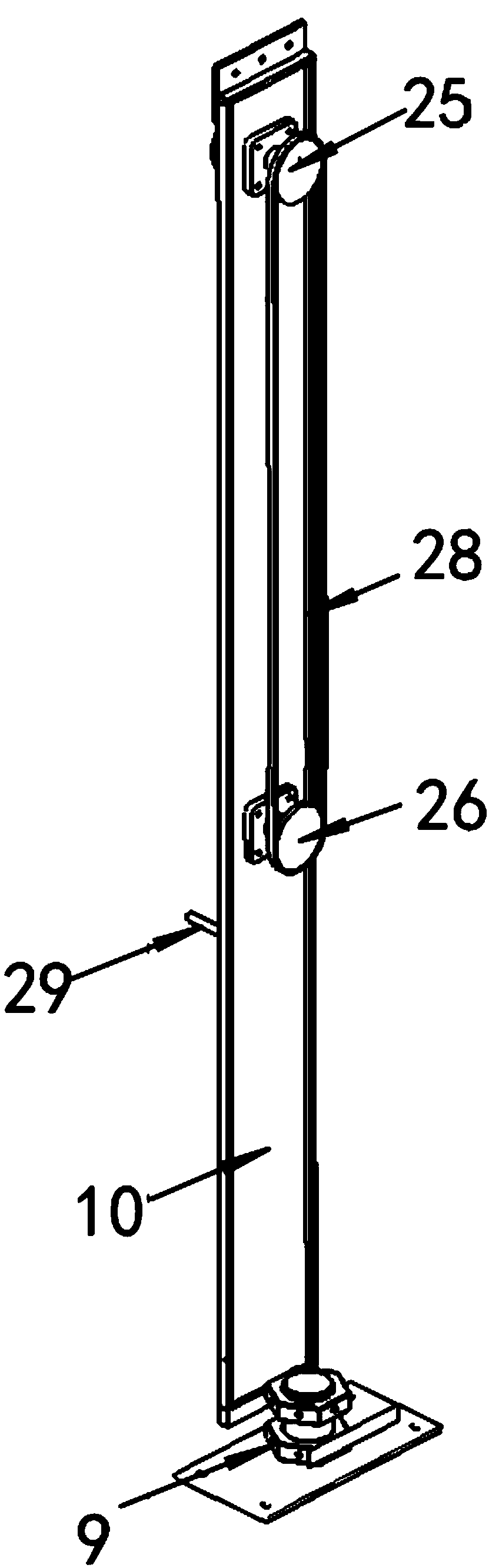
[0017] The following examples refer to Figure 1-6 .

[0018] The semi-automatic electromagnetic riveting device for conical cylindrical structural parts of the present invention includes a fixed support frame 1 , a support column assembly 2 , a riveting execution assembly 3 and a positioner assembly 4 . The crossbeam 7 of the fixed support frame 1 is fixedly connected with the fixed box 11 of the riveted executive assembly 3 through the connecting plate 8, and the bottom plate 5 of the fixed support frame 1 is fixed on the foundation by anchor bolts to play a role of fixed support; the support column assembly 2 The supporting column 10 and the fixed box 11 of the riveting executive assembly 3 are connected by bolts, the lower end of the supporting column assembly 2 is fixed on the foundation through the adjustable base 9 of the supporting column, and the level of the fixed box 11 is ensured by adjusting the supporting height; the riveting executive assembly 3 Ensure that the...


PUM


Abstract

The invention discloses a semi-automatic electromagnetic riveting device of a conical-tubular-structure workpiece. The device is used for solving the technical problem that an existing electromagneticriveting device is poor in practicability. According to the technical scheme, the device consists of a fixing and supporting frame, a support column assembly, a riveting execution assembly and a displacement machine assembly. The fixing and supporting frame and the support column assembly are used for fixing and supporting the riveting execution assembly, the riveting execution assembly adjusts the position of an electromagnetic riveting gun and a jacking iron to rivet a workpiece, the displacement machine assembly positions and clamps the workpiece and moves the workpiece to the accurate position. The fixing and supporting frame and the support column assembly enable a fixing box to be horizontally and stably placed; the displacement machine assembly achieves displacement, turnover and rotation of the workpiece, so that the to-be-riveted position of the workpiece can be conveniently adjusted; and the riveting execution assembly enables the electromagnetic riveting gun and the jackingiron to move up and down, so that the electromagnetic riveting gun is convenient to enter the workpiece, and the technical problem that the conical-tubular-structure workpiece is difficult to rivet is solved. Through a transition disc, a lead screw and a clamping jaw, quick clamping and fastening of the workpiece is achieved, and the practicability is good.

Description

technical field [0001] The invention relates to an electromagnetic riveting device, in particular to a semi-automatic electromagnetic riveting device for a tapered cylindrical structural part. Background technique [0002] The document "Application Publication No. CN105562580A Chinese Invention Patent" discloses a semi-automatic electromagnetic riveting system for conical shell-like structural parts, which consists of a frame linkage assembly, a riveting gun assembly, and a top handle assembly. Bolted with the riveting gun assembly and the top handle assembly respectively, the riveting of the semi-conical shell structural parts can be realized, the single-person operation of the riveting system is realized, the labor intensity of workers is reduced, and the safety of semi-conical shell structural workpieces is improved. Riveting quality. However, the above-mentioned patent cannot install a complete cone-shaped cylindrical structure, and only realizes the riveting of the sem...

Claims


Application Information

Patent Timeline
Patent Type & Authority Applications(China)
IPC IPC(8): B21J15/24B21J15/38
CPCB21J15/24B21J15/38
Inventor 曹增强党成龙杨宝惠魏凌峰郑国常亚南
Owner SHAANXI DAGONG XUHANG ELECTROMAGNETIC TECH CO LTD
Why Eureka
Try Eureka