Broaching force detection device and detection method thereof

A detection device and detector technology, applied in the field of sensors

Active Publication Date: 2019-04-16
HANGZHOU DIANZI UNIV
View PDF8 Cites 2 Cited by
  • Summary
  • Abstract
  • Description
  • Claims
  • Application Information

AI Technical Summary

Problems solved by technology

There are detectors in eac

Method used


Image

  • Broaching force detection device and detection method thereof
  • Broaching force detection device and detection method thereof
  • Broaching force detection device and detection method thereof

Examples


Embodiment Construction

[0030] The present invention will be further described below in conjunction with accompanying drawing.

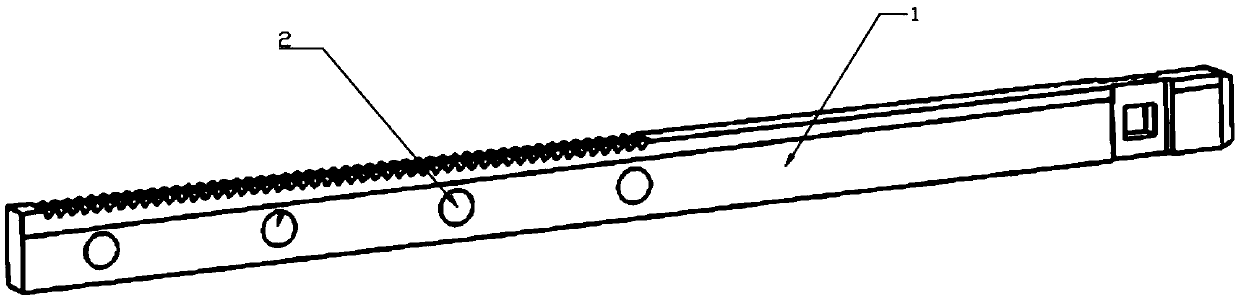
[0031] Such as figure 1 , 2 , 3 and 4, a broaching force detection device includes a broach body 1, a sealing cover 2 and a detector. The broach body 1 adopts a keyway type broach. The blade body side of the broach body 1 is provided with four placement through slots. The four placement through slots are arranged at equal intervals in sequence along the length direction of the knife body. Detectors are arranged in the four placement through slots.

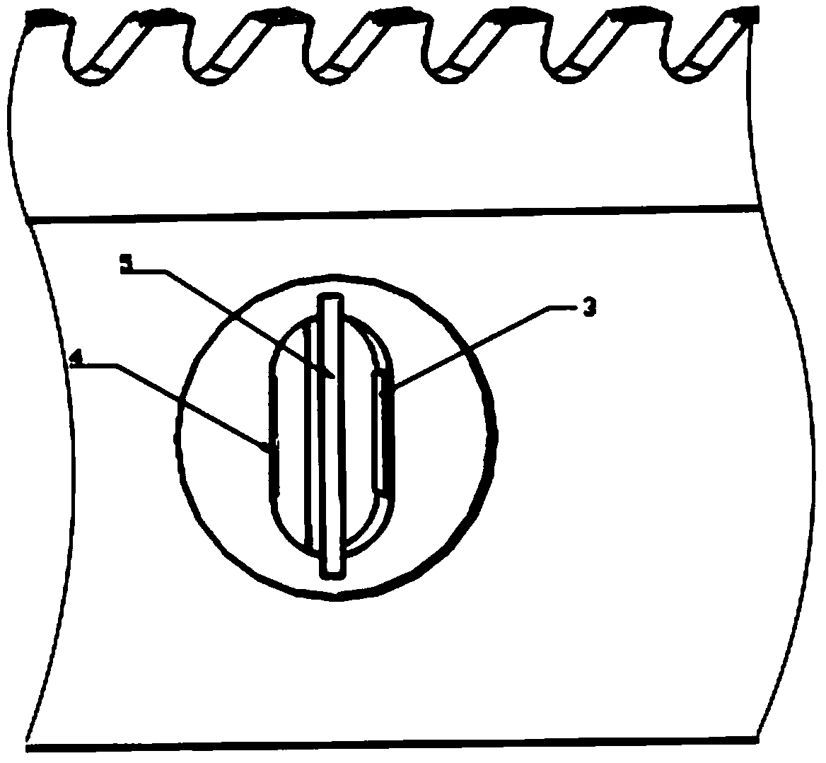
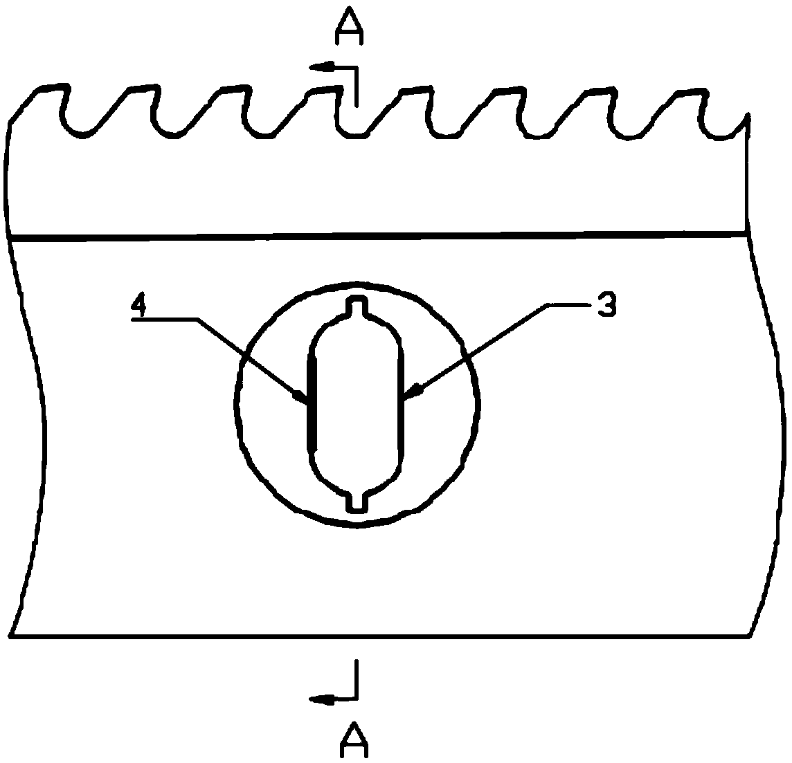
[0032] The detector includes a strain sensor 3 , a piezoelectric sheet 4 and a circuit substrate 5 . The strain sensor 3 and the piezoelectric sheet 4 are arranged on both sides of the installation through groove respectively, and the distance between the piezoelectric sheets in the four installation through grooves and the strain sensor is equal. The joints between the placement through slots, the strain sensor 3 and the ...


PUM


Abstract

The invention discloses a broaching force detection device and a detection method thereof. Due to the particularity of a broaching machining technology, a general cutting force detection device cannoteffectively detect the size of broaching load. The device and the method thereof involve a self-detection broach with a vibration energy collecting function and comprises a broach body and detectors.N placement through grooves are formed in the side portion of a broach body of the broach body. The detectors are arranged in the n placement through grooves. Each detector comprises a strain sensor,a piezoelectric plate and a circuit base board, wherein the strain sensor and the piezoelectric plate are arranged on the two sides of the corresponding placement through groove correspondingly, thecircuit base board is fixed in the corresponding placement through groove, the circuit base board is provided with a detection-energy collection circuit, and the detection-energy collection circuit comprises an energy collection module, a broaching load detection module and a wireless transmission module. According to the device and the method thereof, the sensors and a cutting part are combined to realize integration measurement of cutting force, so that the measurement of the cutting force is not limited by the size of a machining space any more.

Description

technical field [0001] The invention belongs to the technical field of sensors, and in particular relates to a broaching force detection device and a detection method thereof. Background technique [0002] Cutting force is one of the main physical phenomena in the process of metal cutting. Its magnitude directly affects cutting heat, machined surface quality, tool wear and tool durability, etc. The continuous change of axial component force in the process of machining affects the surface quality of the workpiece. The axial component force also has a great influence on the shape accuracy of the workpiece. It can be seen that every slight change in the cutting state can be reflected by the value of the cutting force, such as tool wear, machine tool failure and chatter during machining. The phenomenon can also be found in time through the monitoring of cutting force. It can be seen that the change of cutting force runs through the entire cutting process, so real-time and accur...

Claims


Application Information

Patent Timeline
IPC IPC(8): B23D39/00B23D41/00B23Q17/09
CPCB23D39/00B23D41/00B23Q17/0971
Inventor 许明何龙陈国金
Owner HANGZHOU DIANZI UNIV
Why Eureka
Try Eureka