Machining method of reverse chamfers

A processing method and reverse technology, applied in the key manufacturing process of key mechanical parts, to achieve the effects of reducing scrap loss, simple fixing and disassembly, and simple structure

Inactive Publication Date: 2019-04-16
SHANGHAI JIKEJIA PRECISION TECH
View PDF9 Cites 0 Cited by
  • Summary
  • Abstract
  • Description
  • Claims
  • Application Information

AI Technical Summary

Problems solved by technology

[0003] The purpose of the present invention is to provide a processing method for reverse chamfering, which fundamentally solves the technical difficulties of fast chamfering that cannot be effectively carried out from bottom to top for precise one-time molding due to the limitation of the internal space of the part, and solves the above technical problems. Overcome the existing defects of the above-mentioned prior art

Method used


Image

  • Machining method of reverse chamfers
  • Machining method of reverse chamfers
  • Machining method of reverse chamfers

Examples


Embodiment Construction

[0023] The present invention will be further described below in conjunction with the accompanying drawings and specific embodiments.

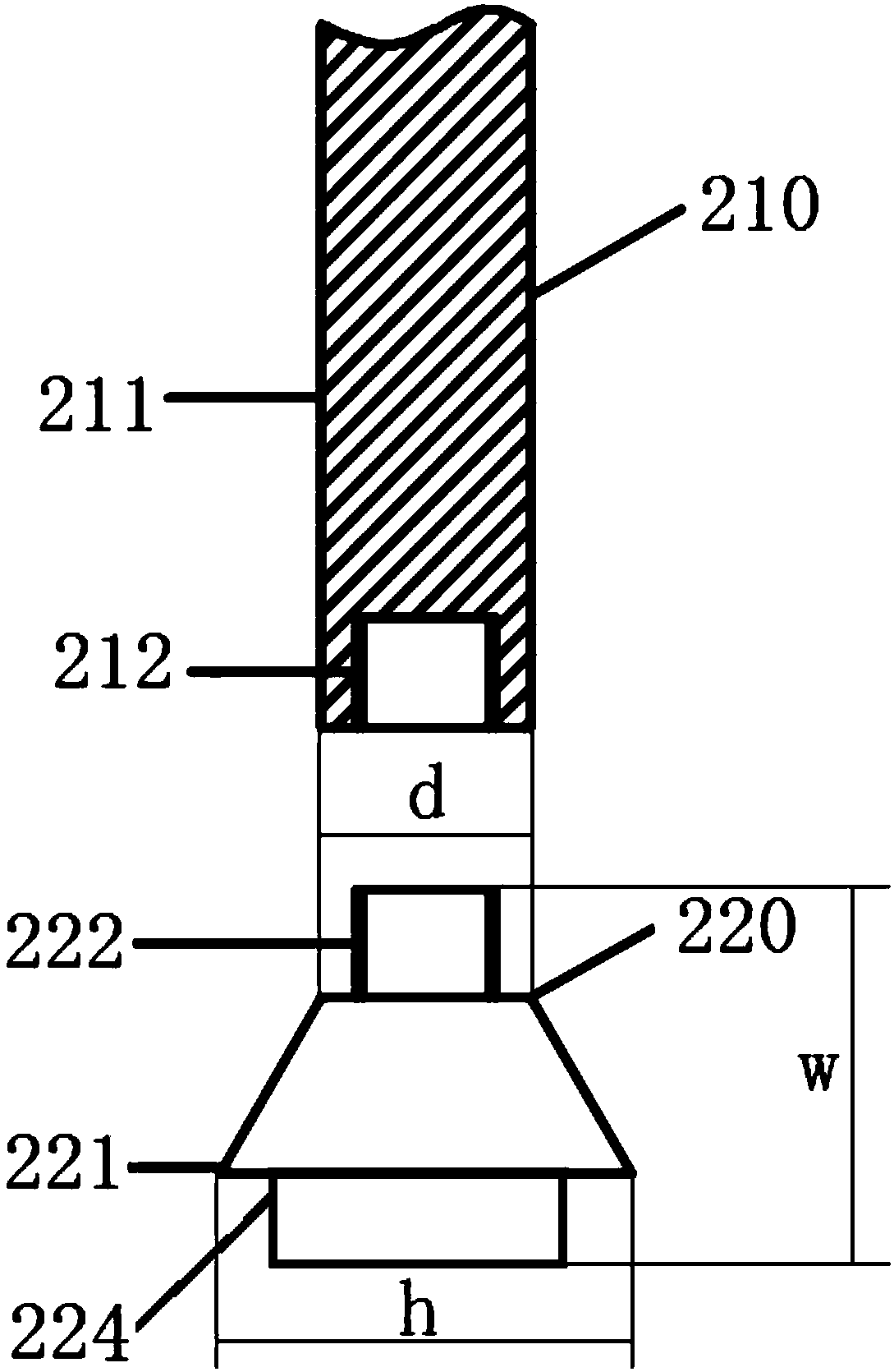
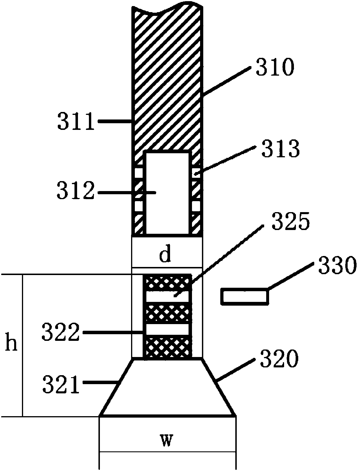
[0024] A processing method of reverse chamfering provided by the present invention adopts three kinds of reverse chamfering knives, which are respectively: handle-locked reverse chamfering knife, cutter head-locked reverse chamfering knife and bolt-fixed Type reverse chamfering knife. The structure of the three kinds of knives will be described first.

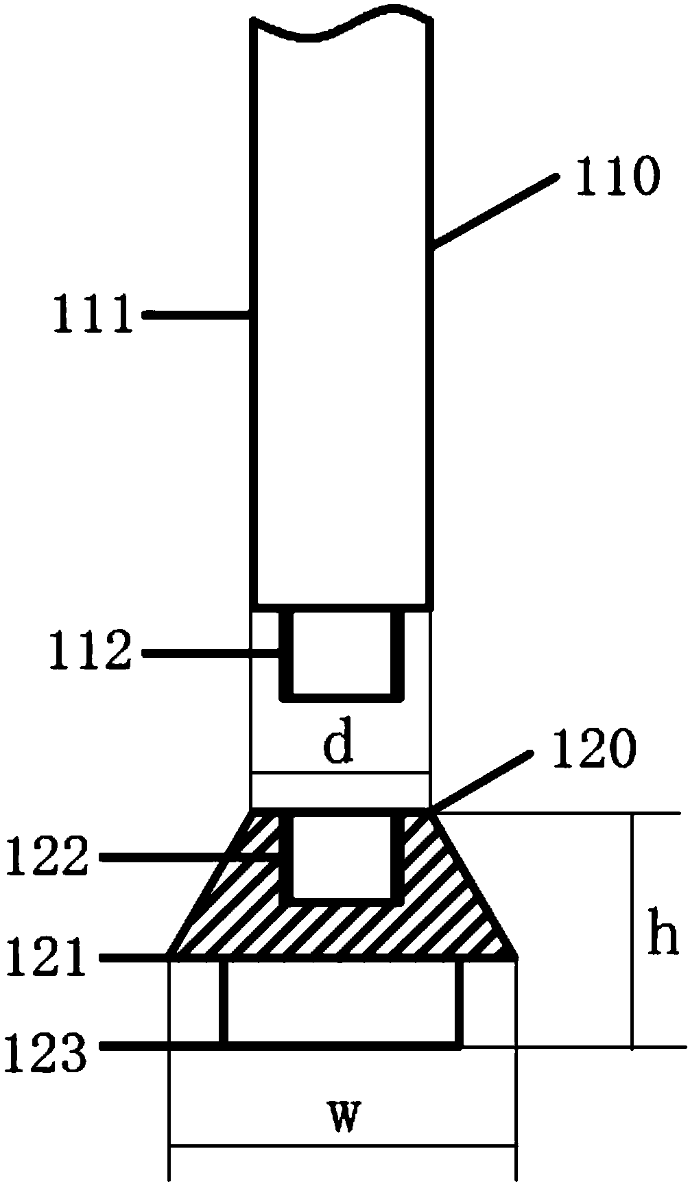
[0025] figure 1 It is the structural diagram of the shank locking type reverse chamfering tool.

[0026] like figure 1 As shown, the shank-locking reverse chamfering knife includes: a shank 110 and a knife head 120 . The handle 110 includes: a handle rod 111 and an external thread 112 . The outer thread 112 is at the bottom of the handle 111 , and the outer diameter of the outer thread 112 is smaller than the outer diameter of the handle 111 . The cutter head 120 is composed of a cutting b...


PUM


Abstract

The invention provides a machining method of reverse chamfers. The machining method includes the following steps that a reverse chamfering knife is assembled; a knife handle penetrates from one end ofa to-be-chamfered hole into an inner cavity in the other end of the to-be-chamfered hole; a knife bit of a cutting body being a truncated cone directly enters the inner cavity from the other end of the to-be-chamfered hole; the knife handle and the knife bit are fixedly connected; the reverse chamfers are machined; and the knife handle drives the knife bit to rotate, and the to-be-chamfered holeis subjected to reverse chamfer machining through a cutting blade on the side face of the truncated cone. The machining method has the beneficial effects that the proper type or dismounting and mounting manner of the chamfer machining knife is selected according to the requirements of different machining sizes and different limited spaces of products, thus, precise chamfering is carried out from bottom to top, the technical requirements of the products are met, the advanced level of the industry is reached, and the quality defects at different degrees that due to manual unreasonable operation,the interiors of parts are not uniformly chamfered, burrs are left, and internal scratches are generated are completely overcome.

Description

technical field [0001] The invention relates to the technical field of precision machinery manufacturing, in particular to a key manufacturing process aspect of a key mechanical component. Background technique [0002] With the rapid development of the domestic precision machining field, some complex components dominated by foreign countries have gradually been localized. However, due to the limitations of equipment, technical methods, personnel experience, processing tools and other factors, some key technical points cannot be efficiently broken through. . At present, many valve body cavity parts with complex structures involve split-layer processing, complex distribution of internal holes, and strict requirements for burr chamfering. Most of the existing inner hole reverse chamfering tools are tool handles and tool heads. The price is expensive, the operation process is not ideal, and the processing quality is unstable. In the absence of a more reasonable solution, most ...

Claims


Application Information

Patent Timeline
IPC IPC(8): B23D79/02
CPCB23D79/02
Inventor 霍佳玉郝景章
Owner SHANGHAI JIKEJIA PRECISION TECH
Why Eureka
Try Eureka