Automobile hub grinding device
A technology for automobile hubs and bevel gears, which is applied in the direction of grinding drive devices, grinding machines, grinding workpiece supports, etc., and can solve problems such as blockage, low production efficiency, and complicated operation steps
- Summary
- Abstract
- Description
- Claims
- Application Information
AI Technical Summary
Problems solved by technology
Method used
Image
Examples
Embodiment 1
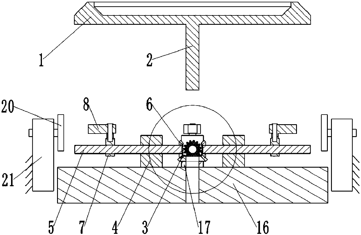
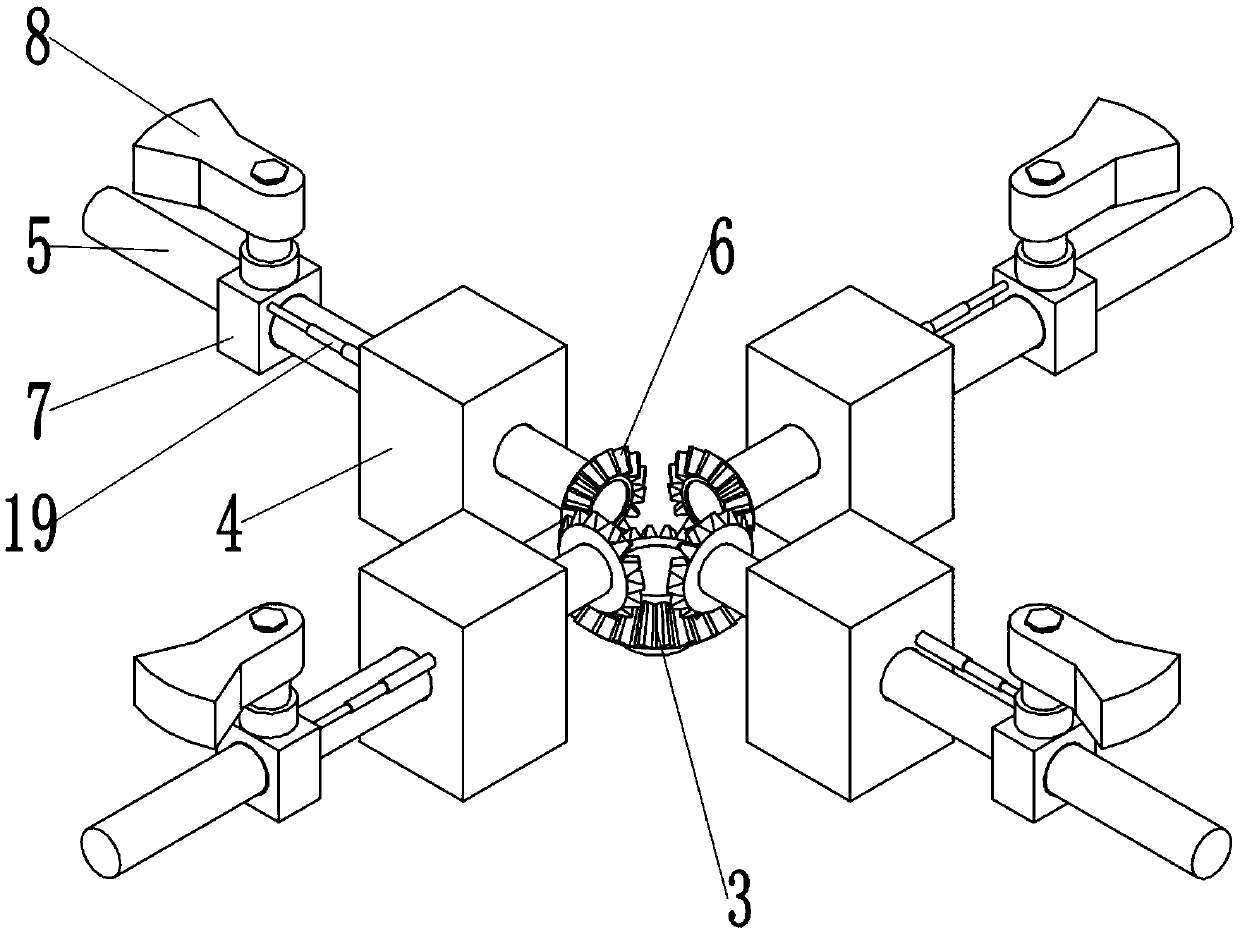
[0031] like figure 1 As shown, the device for grinding automobile wheels includes a frame and a positioning mechanism. The positioning mechanism includes a horizontal positioning assembly and a vertical stopper. The outer peripheral wall of the shaft 2 is processed with external threads, and the frame is rotatably connected with an operating table 16, which is located below the positioning mechanism, and the operating table 16 is rotatably connected with a driven cone for threaded connection with the driving shaft 2 through the rotating shaft 17. Gear 3, such as Figure 5 As shown, the specific connection method is as follows: the driven bevel gear 3 is fixedly connected to the rotating shaft 17, and the rotating shaft 17 is rotationally connected to the operating table 16, and a bearing is arranged between the rotating shaft 17 and the operating table 16, and the rotating shaft 17 is connected along the axis There is a through hole for the drive shaft 2 to pass through in th...
Embodiment 2
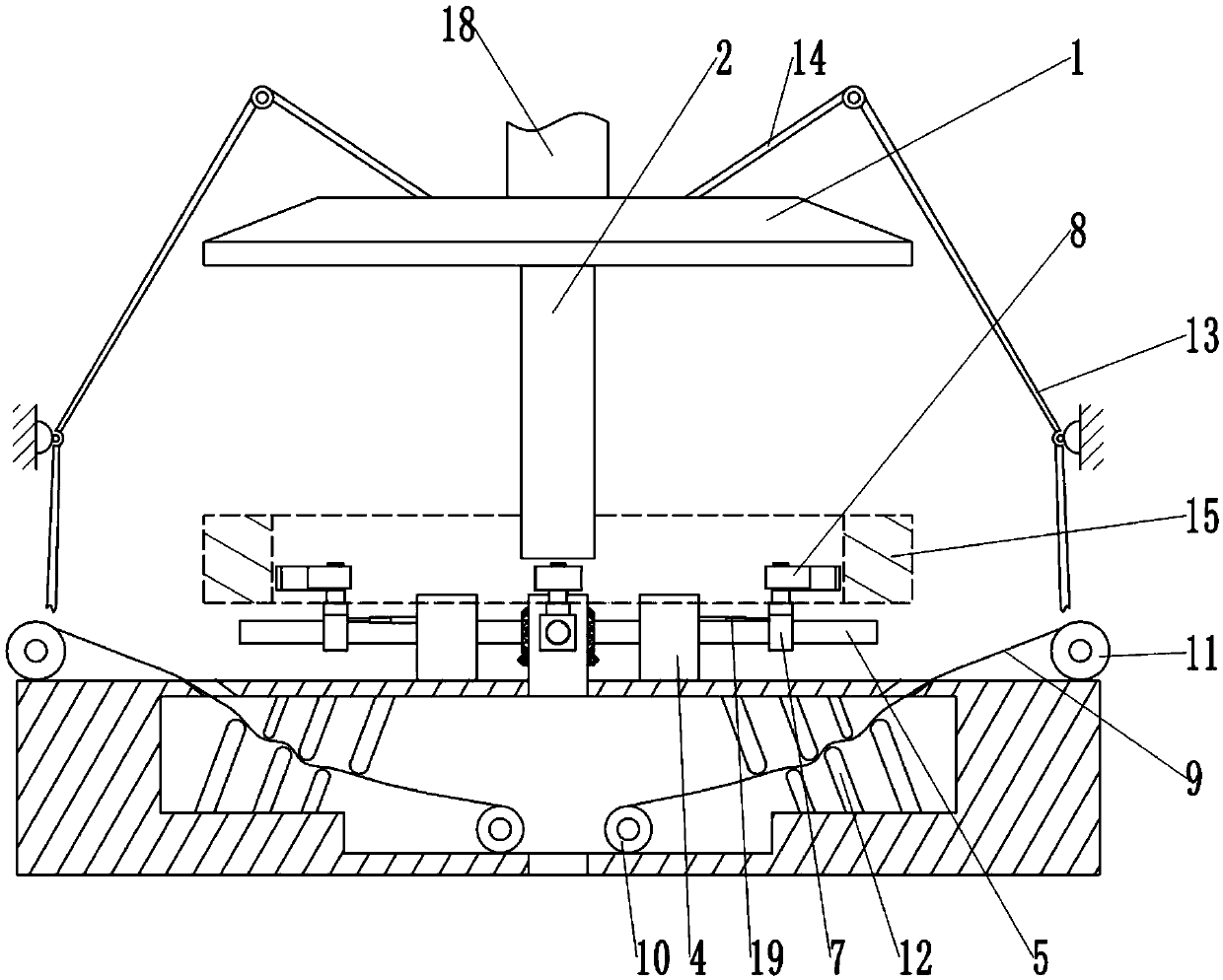
[0037] like image 3 As shown, the difference between the present embodiment and the first embodiment lies in the structure and quantity of the cleaning mechanism. This embodiment is provided with two cleaning mechanisms with the same structure to image 3 Take the cleaning mechanism on the right side as an example to describe its structure in detail:
[0038] The cleaning mechanism comprises a dust collection cover 9, an active winding roller 10 and a passive winding roller 11. The console 16 adopts a hollow structure, and the top of the console 16 is provided with a channel for passing the dust collection cover 9, and the active winding roller 10 is rotated and installed in the operating table 16, and the passive winding roller 11 is slidably arranged above the operating table 16, and the active winding roller 10 and the passive winding roller 11 stretch the dust collection cover 9 under the positioning mechanism; the dust collection cover The left end of 9 passes through ...
PUM
 Abstract
Description
Claims
Application Information
 - R&D
- Intellectual Property
- Life Sciences
- Materials
- Tech Scout
- Unparalleled Data Quality
- Higher Quality Content
- 60% Fewer Hallucinations
Browse by: Latest US Patents, China's latest patents, Technical Efficacy Thesaurus, Application Domain, Technology Topic, Popular Technical Reports.
© 2025 PatSnap. All rights reserved.Legal|Privacy policy|Modern Slavery Act Transparency Statement|Sitemap|About US| Contact US: help@patsnap.com


