Novel mechanical gripper with pressure buffer structure

A cushioning structure and mechanical gripper technology, which is applied in the direction of manipulators, manufacturing tools, chucks, etc., can solve the problems of small clamping force, inability to clamp items, and clamping jaws without pressure buffer structure, so as to prevent damage to items Effect

Pending Publication Date: 2019-04-16
周博文
View PDF0 Cites 14 Cited by
  • Summary
  • Abstract
  • Description
  • Claims
  • Application Information

AI Technical Summary

Problems solved by technology

[0002] Nowadays, in order to improve the efficiency of the factory, the factory begins to use industrial robots to replace manual labor to perform some mechanized repetitive work. Robots need mechanical grippers to pick up objects, but most of the existing ordinary mechanical grippers are pneumatic grippers. , Most of these jaws do not have a pressure buffer structure, and they cannot control and adjust the strength of the jaws well when picking up items. The stability is relatively poor. When the air pressure is too high, the clamping force will increase, resulting in the items being held damage, when the air pressure is low, the clamping force may be small, and the item cannot be clamped; and after the mechanical gripper clamps the item, it is mostly carried by the rotation of the mechanical arm, because the ordinary gripper is held by air pressure. The instability of the clamping force and the air pressure often cause the item to fall from the mechanical gripper, so we provide a new type of mechanical gripper with a pressure buffer structure

Method used


Image

  • Novel mechanical gripper with pressure buffer structure
  • Novel mechanical gripper with pressure buffer structure
  • Novel mechanical gripper with pressure buffer structure

Examples


Embodiment Construction

[0027] The following will clearly and completely describe the technical solutions in the embodiments of the present invention with reference to the accompanying drawings in the embodiments of the present invention. Obviously, the described embodiments are only some, not all, embodiments of the present invention. Based on the embodiments of the present invention, all other embodiments obtained by persons of ordinary skill in the art without making creative efforts belong to the protection scope of the present invention.

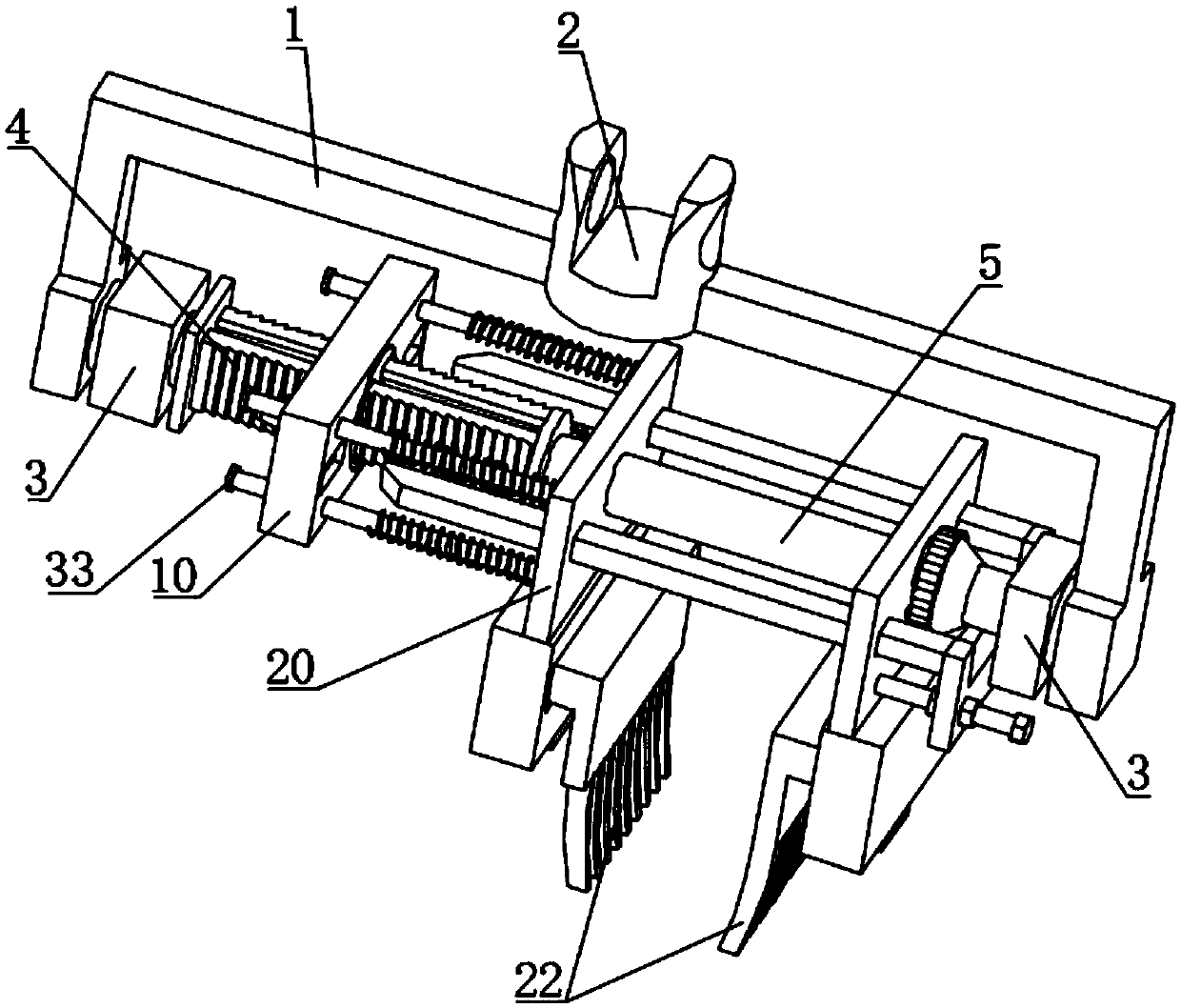
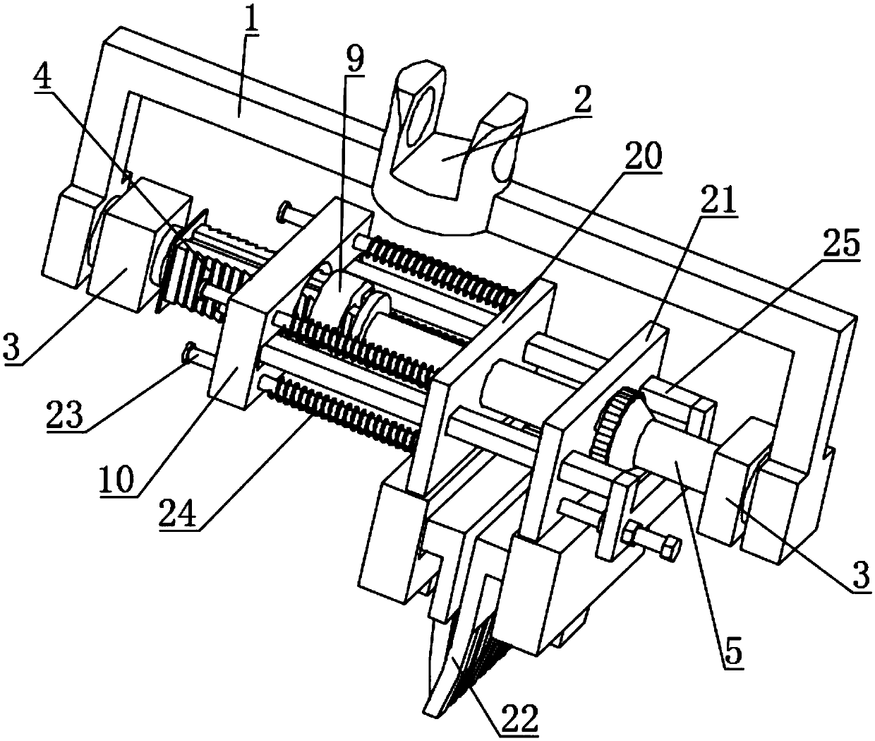
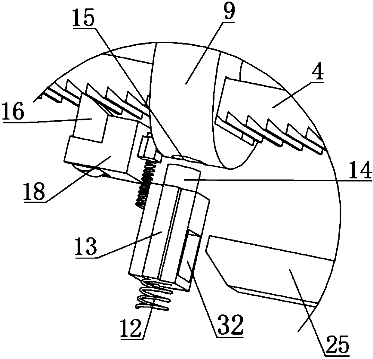
[0028] see Figure 1-12 , the present invention provides a new technical solution for a mechanical gripper with a pressure buffer structure, including a bracket 1, the middle part of the bracket 1 is fixedly connected with an articulated joint 2, and the articulated joint 2 is rotatably connected to the end of the mechanical arm of an industrial robot. After the device clamps the object, the position of the device is changed by the rotation of the mechanical a...


PUM


Abstract

The invention discloses a novel mechanical gripper with a pressure buffer structure. The novel mechanical gripper with the pressure buffer structure comprises a support connected with an external mechanical arm; the two ends of the support are connected with bases, a first guide rod and a second guide rod are arranged between the bases, the first guide rod is sleeved with a regulating block, and the second guide rod is slidably sleeved with a first slide plate and a second slide plate; the lower sides of the first slide plate and the second slide plate are fixedly connected with claws; the right side wall of the first slide plate is fixedly connected with a plurality of guide pillars; the portion, between the regulating block and the first slide plate, of the outer side wall of each guidepillar is sleeved with a third spring; and the second slide plate is provided with ejector rods. The novel mechanical gripper with pressure buffer structure can make the regulating block slide to theright through the screw rod rotation, so that the regulating block pushes the first slide plate to slide through the third spring, and the two claws approach slowly and then clamp objects; and the third spring acts as a clamping buffer and makes the device more stable when the device grasps the objects.

Description

technical field [0001] The invention relates to the technical field of industrial manipulators, in particular to a novel manipulator gripper with a pressure buffer structure. Background technique [0002] Nowadays, in order to improve the efficiency of the factory, the factory begins to use industrial robots to replace manual labor to perform some mechanized repetitive work. Robots need mechanical grippers to pick up objects, but most of the existing ordinary mechanical grippers are pneumatic grippers. , Most of these jaws do not have a pressure buffer structure, and they cannot control and adjust the strength of the jaws well when picking up items. The stability is relatively poor. When the air pressure is too high, the clamping force will increase, resulting in the items being held damage, when the air pressure is low, the clamping force may be small, and the item cannot be clamped; and after the mechanical gripper clamps the item, it is mostly carried by the rotation of t...

Claims


Application Information

Patent Timeline
Patent Type & Authority Applications(China)
IPC IPC(8): B25J15/00B25J15/08
CPCB25J15/00B25J15/08
Inventor 不公告发明人
Owner 周博文
Why Eureka
Try Eureka