Melon and fruit cutting device
A cutting device, melon and fruit technology, applied in metal processing and other directions, can solve the problems of unstable melon and fruit, poor cutting effect, inability to fix melon and fruit, etc., and achieve the effect of improving the scope of application and convenient pushing.
- Summary
- Abstract
- Description
- Claims
- Application Information
AI Technical Summary
Problems solved by technology
Method used
Image
Examples
Embodiment 1
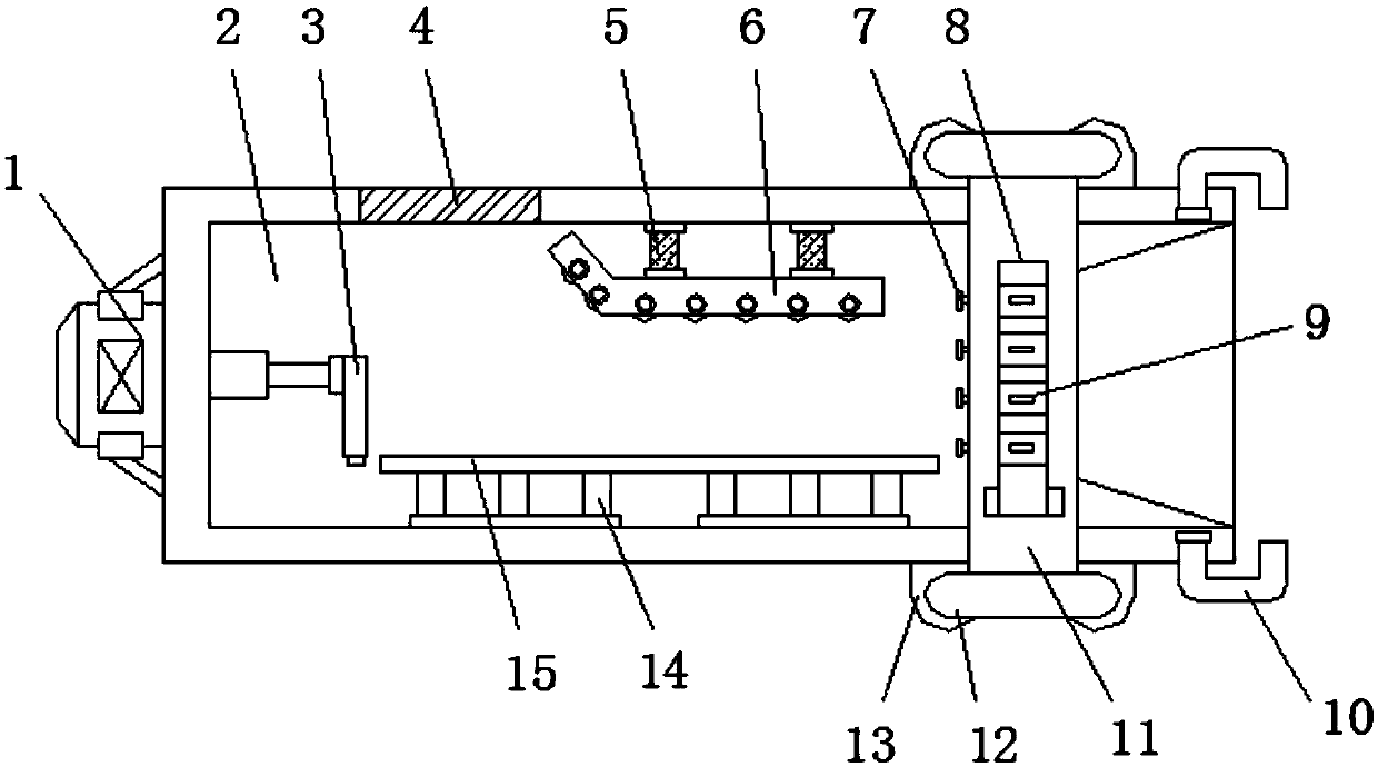
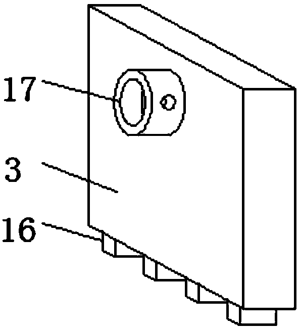
[0024] Embodiment 1, with reference to Figure 1-5 , a melon and fruit cutting device, including a cutting table 2, one end of the cutting table 2 is fixed with a hydraulic machine 1 through a frame bolt, the piston rod of the hydraulic machine 1 extends to the inside of the cutting table 2, and the free end of the piston rod of the hydraulic machine 1 passes through a connecting sleeve 17 The pusher plate 3 is sleeved, and the other end of the cutting table 2 is rotationally connected with a connecting piece 10, and the connecting piece 10 and the piston rod of the hydraulic machine 1 are fixed by screws, so that the pushing plate 3 can be disassembled, and the cutting table 2 The inner wall on one side is connected with the dynamic pressure plate 6 through the elastic member 5, and the inner wall on the other side of the cutting table 2 is connected with the flat plate 15 through the connecting rod 14. The elastic force of the elastic member 5 can make the dynamic pressure pl...
Embodiment 2
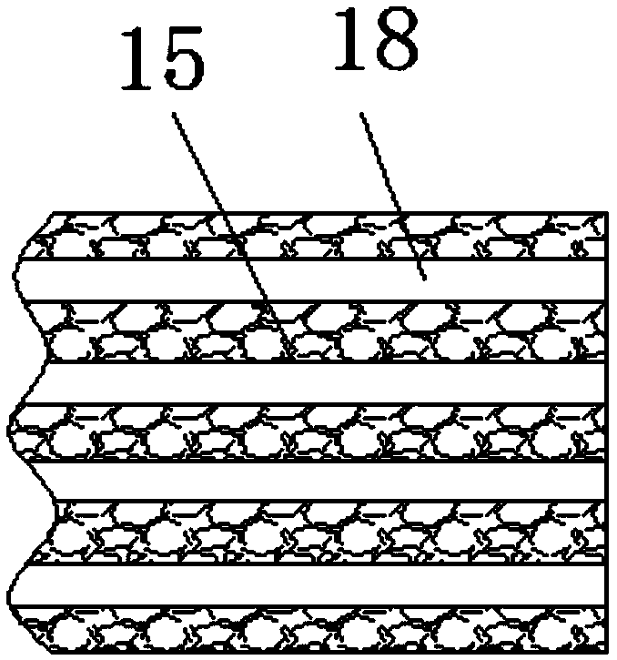
[0026] Embodiment 2, with reference to Figure 1-3 One side of the pusher plate 3 is welded with a alignment plate 16, and the outer surface of the flat plate 15 is equidistantly provided with a plurality of alignment grooves 18, and the alignment grooves 18 fit with the alignment plate 16. When the plate 3 pushes the material to move to the position of the cutter 21, the side of the material pushing plate 3 is always in a state of bonding with the surface of the flat plate 15, which facilitates the pushing of the material.
Embodiment 3
[0027] Embodiment 3, with reference to figure 1 with image 3 , the side of the dynamic pressure plate 6 is regarded as a U-shaped structure, and the two vertical ends of the dynamic pressure plate 6 are rotatably connected with the auxiliary roller shaft 20 through the bearing 19, and the radius of the auxiliary roller shaft 20 is greater than that of the center point of the bearing 19 to the vertical end of the dynamic pressure plate 6 The distance between the ports can be pushed more conveniently when the material is squeezed between the flat plate 15 and the auxiliary roller 20 through the effect of the auxiliary roller 20, and the surface of the material will not be affected by friction. The auxiliary roller 20 is provided with multiple , and the spacing between the plurality of auxiliary rollers 20 is equal, and the end of the dynamic platen 6 close to the feed port 4 is an inclined structure. This structure is provided so that materials of different sizes can be limited...
PUM
 Abstract
Description
Claims
Application Information
 - R&D
- Intellectual Property
- Life Sciences
- Materials
- Tech Scout
- Unparalleled Data Quality
- Higher Quality Content
- 60% Fewer Hallucinations
Browse by: Latest US Patents, China's latest patents, Technical Efficacy Thesaurus, Application Domain, Technology Topic, Popular Technical Reports.
© 2025 PatSnap. All rights reserved.Legal|Privacy policy|Modern Slavery Act Transparency Statement|Sitemap|About US| Contact US: help@patsnap.com


