

Bundling component of electronic yarn drawing equipment
An electronic yarn and clustering technology, which is applied in the clustering of newly extruded filaments, textiles and papermaking, etc., can solve the problems of small space in the cluster bracket, affecting quality, and increased maintenance, so as to reduce maintenance work and facilitate the adjustment process , Reduce the time-consuming effect of adjustment
- Summary
- Abstract
- Description
- Claims
- Application Information
AI Technical Summary
Problems solved by technology
Method used
Image

Examples
Embodiment 1
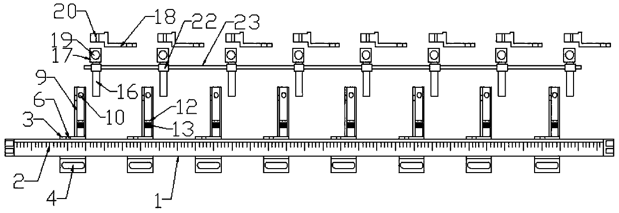
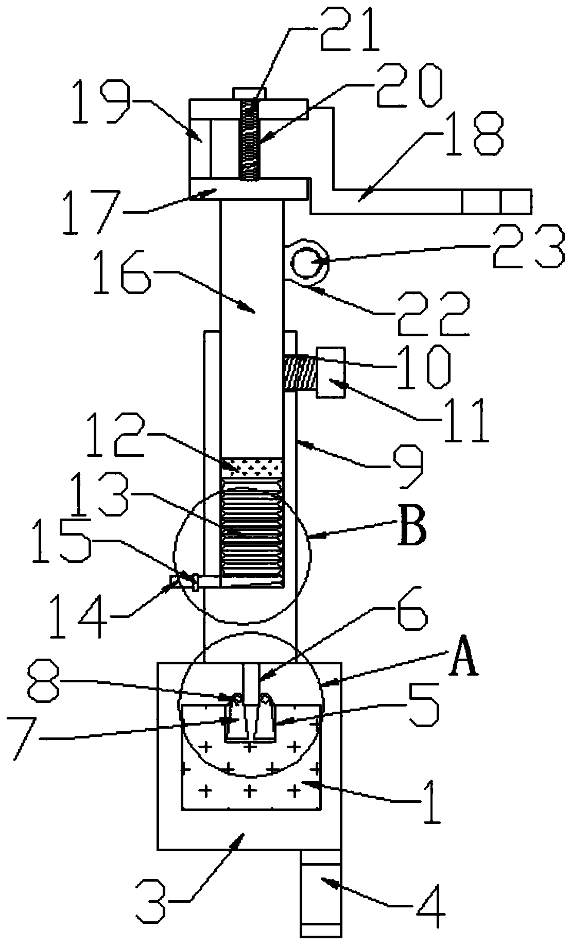
[0034] Such as Figure 1-4 As shown, a clustering part of an electronic yarn drawing equipment includes a stainless steel bar 1, a slider 3, a fixed rod 9, an adjustable vertical rod 16, and a clustering wheel bracket 18. Several sliders 3 are set on the stainless steel bar 1, A fixed rod 9 is welded on each slider 3, and an adjustable vertical rod 16 is inserted on the fixed rod 9, and is locked and fixed with the first bolt 11. The top of the adjustable vertical rod 16 is also welded with a mounting block 17. The connecting end of the wheel bracket 18 is inserted into the mounting groove 19 provided on the mounting block 17, and is locked and fixed with the second bolt 21. The upper side of the adjustable vertical rod 16 is also welded with a collar 22, and several collars 22 are inner sleeves. The same long rod 23 is provided.
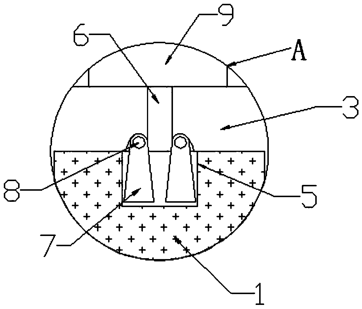
[0035] The stainless steel bar 1 is provided with a card slot 5, and the slider 3 is provided with a positioning bolt hole 6. Both sides of the bo...
Embodiment 2
[0038] Such as Figure 1-4 As shown, a receiving plate 12 is placed in the fixed rod 9, and the receiving plate 12 is connected to the fixed rod 9 through the foldable airbag 13, and the lower side of the foldable airbag 13 is also connected with an air intake pipe 14, and the air intake pipe 14 passes through the fixed rod 9. An air valve 15 is also installed on the air intake pipe 14. The air valve 15 controls the on-off of the air intake pipe 14, inflates the foldable airbag 13 through the air intake pipe 14, and uses the air pressure to drive the receiving plate 12 to rise, so that the receiving plate 12 drives The adjustable vertical rod 16 on it moves up and down in the fixed rod 9.
[0039] The upper side of the fixed rod 9 is also provided with a first bolt hole 10, and the first bolt hole 10 is internally threaded with a supporting first bolt 11, and the adjustable vertical rod that is sleeved in the fixed rod 9 is connected by the first bolt 11. 16 Fasten to prevent...
PUM
 Abstract
Description
Claims
Application Information