Combined energy dissipator

An energy-dissipating and energy-dissipating technology, applied in water conservancy projects, marine engineering, coastline protection, etc., can solve the problems of low energy-dissipation efficiency, large-scale energy-dissipating workers, and large engineering volume, and achieves reasonable design and improved energy consumption. Energy efficient and compact

Pending Publication Date: 2019-04-16
中水淮河规划设计研究有限公司
View PDF14 Cites 2 Cited by
  • Summary
  • Abstract
  • Description
  • Claims
  • Application Information

AI Technical Summary

Problems solved by technology

[0002] The problem of energy discharge is often a major and complex scientific and technical problem in the design of large-scale water conservancy and hydropower projects. It requires comprehensive consideration of the relationship and rational layout of water-retaining buildings, water-discharging buildings and building-making buildings. And according to the topography, geology and hydrological conditions of the dam site, the form of the discharge structure and the safe and reliable energy dissipation method are reasonably selected. The traditional energy dissipation methods commonly used mainly include wide tail piers, energy dissipation steps, stilling pools, etc. or a combination thereof. Two combinations, but the traditional energy dissipation method of single or pairwise combination requires the energy dissipation worker to be too large, which has the disadvantages of high cost, large amount of engineering, and low energy dissipation efficiency

Method used


Image

  • Combined energy dissipator
  • Combined energy dissipator
  • Combined energy dissipator

Examples


Embodiment 1

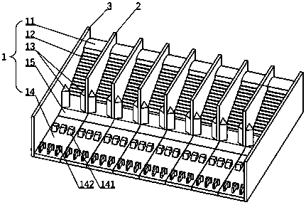
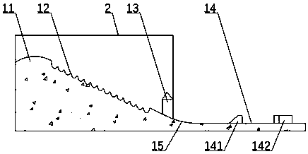
[0022] Such as Figure 1-3 As shown, a combined energy dissipator includes a plurality of energy dissipator monomers 1 arranged side by side. 14. The step section of the energy-dissipating step 12 is in the lower part of a vertical ellipse. The upper end of the energy-dissipating step 12 is connected to the top of the overflow dam 11, and the lower end is connected to the front end of the wide tail pier 13. The rear end of the tail pier 13 is connected to the stilling pool 14 through an anti-arc section 15; a gate pier 2 is arranged between the energy dissipation units 1, and the gate pier 2 extends from the front end of the overflow dam 11 To the rear end of the wide tail pier 13.

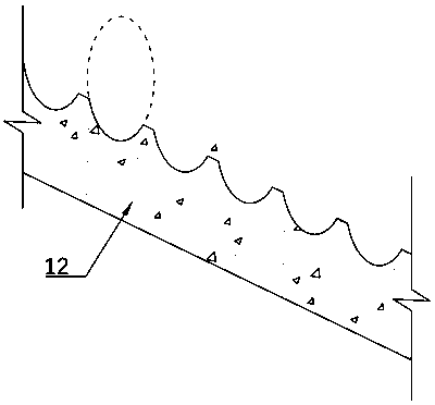
[0023] Preferably, the step section shape of the energy dissipation step 12 is the lower part of a vertical ellipse with a major axis of 2m, a minor axis of 1.75m and an eccentricity of 0.48.

[0024] Preferably, a trapezoidal pier 141 and a T-shaped pier 142 are arranged in the stilling basin. ...

Embodiment 2

[0031] Such as Figure 1-3 As shown, a combined energy dissipator includes a plurality of energy dissipator monomers 1 arranged side by side. 14. The step section of the energy-dissipating step 12 is in the lower part of a vertical ellipse. The upper end of the energy-dissipating step 12 is connected to the top of the overflow dam 11, and the lower end is connected to the front end of the wide tail pier 13. The rear end of the tail pier 13 is connected to the stilling pool 14 through an anti-arc section 15; a gate pier 2 is arranged between the energy dissipation units 1, and the gate pier 2 extends from the front end of the overflow dam 11 To the rear end of the wide tail pier 13.

[0032] Preferably, the step section shape of the energy dissipation step 12 is the lower part of a vertical ellipse with a major axis of 2.25m, a minor axis of 1.25m and an eccentricity of 0.83.

[0033] Preferably, a trapezoidal pier 141 and a T-shaped pier 142 are arranged in the stilling basi...

Embodiment 3

[0040] Such as Figure 1-3 As shown, a combined energy dissipator includes a plurality of energy dissipator monomers 1 arranged side by side. 14. The step section of the energy-dissipating step 12 is in the lower part of a vertical ellipse. The upper end of the energy-dissipating step 12 is connected to the top of the overflow dam 11, and the lower end is connected to the front end of the wide tail pier 13. The rear end of the tail pier 13 is connected to the stilling pool 14 through an anti-arc section 15; a gate pier 2 is arranged between the energy dissipation units 1, and the gate pier 2 extends from the front end of the overflow dam 11 To the rear end of the wide tail pier 13.

[0041] Preferably, the step section shape of the energy dissipation step 12 is the lower part of a vertical ellipse with a major axis of 2.5m, a minor axis of 1.5m and an eccentricity of 0.8.

[0042] Preferably, a trapezoidal pier 141 and a T-shaped pier 142 are arranged in the stilling basin. ...


PUM


Abstract

The invention discloses a combined energy dissipator. The combined energy dissipator comprises a plurality of energy dissipator bodies which are arranged side by side, and each energy dissipator bodycomprises an overflow dam, energy-dissipation steps, flaring piers and a stilling pool, wherein the step profile of each energy-dissipation steps is shaped like the lower part of an ellipse, the upperend of the energy-dissipation steps is connected with the top of the overflow dam, the lower end of the energy-dissipation steps is connected with the front ends of the flaring piers, and the rear ends of the flaring piers are connected with the stilling pool through inverted arc sections. Gate piers are arranged between the energy dissipator bodies, and the gate piers keep extending to the rearends of the flaring piers from the front ends of the overflow dams. By means of the combined energy dissipator, the lengths between the energy-dissipation steps and the stilling pool can be effectively reduced, the engineering quantity is reduced, the engineering cost is reduced, and energy loss can be efficiently reduced.

Description

technical field [0001] The invention belongs to the technical field of flood discharge and energy dissipation for water conservancy and hydropower projects, and in particular relates to an energy dissipation tool. Background technique [0002] The problem of energy discharge is often a major and complex scientific and technical problem in the design of large-scale water conservancy and hydropower projects. It requires comprehensive consideration of the relationship and rational layout of water-retaining buildings, water-discharging buildings and building-making buildings. And according to the topography, geology and hydrological conditions of the dam site, the form of the discharge structure and the safe and reliable energy dissipation method are reasonably selected. The traditional energy dissipation methods commonly used mainly include wide tail piers, energy dissipation steps, stilling pools, etc. or a combination thereof. Two combinations, but the traditional energy diss...

Claims


Application Information

Patent Timeline
Patent Type & Authority Applications(China)
IPC IPC(8): E02B8/06
CPCE02B8/06
Inventor 马东亮杨中祝云宪王桂生胡兆球赵永刚杨峰冯治刚韩福涛
Owner 中水淮河规划设计研究有限公司
Why Eureka
Try Eureka